HOME
What's New

CPU Cooler
Programs
Introduction
AmnHLT
CpuIdle
Rain 
VCool 2.0 
Waterfall Pro 
Current Tests 
Test Archives

UDMA Driver 
Tests 
Windows 95
Windows 98
Windows NT

Way 2 Cool 
Projects 
Compaq 1800T
1800T Temp Monitor
Celeron-A
Going for 504
More on 504
Cheap Sandwich
BX6r2 Diode Fix
Condensation
Lap that Slug
Celeron PPGA
Journey to 1080
Building an NT Box
Heat Pipe 1
Heat Pipe 2
Heat Pipe 2.2
gp_Temp
gp_Temp4
gp_Temp5

Heat Sinks 
Aavid
A&C Prototype Sink
Alpha P125
Alpha P521
CPU Cooler
FullWay
Tom's Sink
Water Cooler 1
Water Cooler 2
Water Cooler 3
Water Cooler 4
*
Water Cooler 6
Water Cooler 7

Way 2 Cool
Thermometer
Thermometer 2
K-6 heat sink
Case Cooling
Heat Sink Tester
More Case Cooling
Klamath heat sink
Q500A Cooling
My Server Temps
Temp Calculators
CKS400 Rack Case
Fan Controller
Cooling Links
Downloads Page

Tips and Trix
Dual Boot Win95 / 98
Dual Boot Linux/NT4
D-B Linux/Win2k
Hot Flash your BIOS

Family Stuff
Prom / St. John
Providenciales

Email Jim


Specs and Materials
The following is a list of parts and materials with sources.  I've also included a template of the hot and cold plates and the insulation.  This page can be downloaded in a MS Word document that will allow you to print the templates in the actual size for cutting and drilling references.

Download  template.doc  130 Kb

Materials
Heat sink (Main)

  • Fullway pin type (presently unavailable in US)                 Fullway's Site
  • 5 ounces and a surface area of about 110 sq. in.


  • I am currently looking into a suitable replacement for the Fullway sink.  I'll let you know when I find one.  If you come across a Celeron slot 1 sink with pins or fins over 1.5 inches high, please let me know.

    Fans

  • (2) 50mm X 10mm heat sink fans (your choice)
  • Use 3 wire fans if you want to monitor RPM.
  • Heat sink (Rear)                                                                    Allstar Shop

  • Aavid Mfr P/N 960-87001

  • (You may substitute one of the cooler plates for this sink.)

    Peltier

  • Part #: 580-0052 30mm X 30mm X 3.3mm TEC             Meci Surplus
  • 127 element Peltier device. 3 Amp, 25 Watts.
  • It draws about 2 amps at 12 volts in my system.
  • "Y" Adapter (to connect peltier to HD power cable)           Radio Shack

  • Part # 278-780  can be adapted. 
  • Plates

  • 3/16" aluminum sheet stock

  • Try a local metal jobber or electronic component surplus house.
    I picked up a used case with enough for about 30 plates for $12.

    Screws, nuts, washers, and springs

  • (4) 6-32 X 1 1/2" flat-heat machine screws
  • (4) 6-32 nuts
  • (4) #6 flat washers
  • (4) #3 brass "finish washers" (used as top spring retainer)
  • (4) 1/4" X 1/2" X.040 coil springs

  • These are available from your local hardware center. Insulation
    I used the top of a styrofoam egg carton. It was the perfect
    thickness for my 3.3mm peltier.  Foam meat trays are nice
    also.  This foam will easily withstand the heat of this application.
    I tested it by attaching it to a bare 100 watt light bulb for a couple
    of hours.  It got soft, but never melted.

    Templates
    Click the link at the top of the page to download the templates in a MS Word Document.
    The word doc will print the templates in the proper size.

    Hot and Cold Plates

    These plates are cut from 3/16" aluminum sheet stock.

    Insulation

    The insulation is sized for a 30mm X 30mm Peltier.
    Trim according to the TEC you use.  The left and right
    edges may also be trimmed to allow a good fit in the
    Celeron's mount on to the motherboard.  I used Abit's
    PII motherboard mount.

    TEC Connection

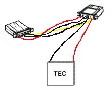
    The TEC was wired to a 486 heat sink fan splitter cable
    I had left over. The splitter is attached in between the hard
    drive and its power connector.  The yellow splitter wire is
    +12 volts and the black is ground.  The positive TEC wire
    (red) is connected to the yellow and black to black.  Make
    sure you power up the TEC to check which side is the cold
    side before mounting it.  Don't run it for longer than necessary
    to determine which is hot and which is cold.

    Assembly


     A hack saw with a 24 tooth per inch blade will suffice for cutting the plates.  I used an 10" aluminum cutting blade on my table saw.  The holes are drilled to a diameter of 7/32", but a little larger hole will allow for some adjustment if the holes do not come out exactly aligned.

    It is important that the mating surfaces are flat and as smooth as you can get them.  This is especially important for mounting the heat plate to the heat sink.  As I discussed in the Celeron article, I use successively finer and finer grades of wet / dry sand paper taped to a piece of glass or other flat surface to lap the surfaces flat.  Before applying thermal compound to the surfaces, you should not be able to see any gap between the plate and sink when held up to a light.  If you come across a heat sink with a thick base (> 3/8"), the heat plate will probably not be necessary.

    There is not too much to the assembly once the plates are cut and drilled.  Make sure that the peltier is installed with the cold side facing the Celeron and that a thin coat of thermal paste is applied between each metal surface.  Tighten the screws in an "X" pattern to keep the pressure constant and to avoid crushing the TEC.  Once the springs are about half way compressed, twist the plates and SEPP back and forth a few times to even out the thermal paste and then tighten the screws until the springs are almost entirely compressed.

    If you decide to build this project, drop me an email and let me know of the outcome.  I'd be interested to get some more input on the success rates.

    Jim
     

    page 1
    Intro
    .
    page 2
    voltage
    limits
    page 3
    high
    volts
    page 4
    trying
    peltiers
    page 5
    second
    attempt
    page 6
    stable
    @ 504
    page 7
    lower
    voltage
    page 8
    case
    heat
    page 9
    final
    thoughts
    page 10
    build
    it