
|
So, finally the new box is up and running. Performance is about where I figured it would be for a P4 - 2.24 gig and a front side bus of 140 (quad pumped speed of 560 MHz). Pretty quick, but the jump from a P3 at 1 gig to a P4 at 2.24 is still not as "seat of the pants" spectacular as my upgrade from a Intel 486-100 (overdrive) to an AMD K6-233 (at 250 - 75 MHz bus). Somehow I don't think I'll ever be as impressed with processor speed as I was with that jump.
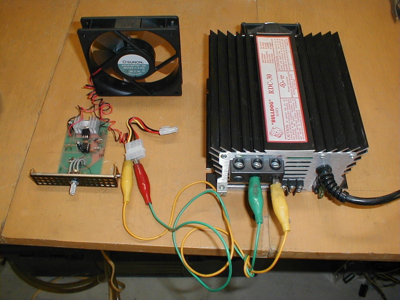
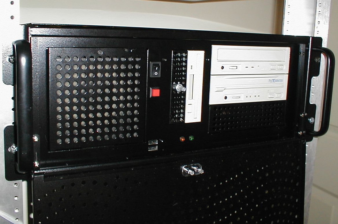
So what do I think of the new system in its rackmount CKS400 case? It's loud. Not "kind of loud." Real loud. Like being on the tarmac behind a 747 when all 4 jets spool up. The sound of the front fan (a Sunon KD 1212PTB1-6A -- rated at: 3100 RPM, 90 CFM, 44.5 dBA noise (so they claim), and .38 Amp) was particularly grating to my ears.
What to do? Tune the fan speed, of course.
With the Sunon in the front of the case and two additional fans in the rear, this case is a veritable wind tunnel. In a server room where noise is not an issue, this box will keep its components cool and no one will care about how loud it is. However, sitting four feet from my head, I was more than willing to trade a bit of performance for a bit of quiet.
I had built a temperature controlled, pulse width modulated speed controller for an earlier project, but found that with the fan's RPM being temperature controlled, sometimes settled on a speed that produced a noise that was bothersome. I thought that this time it would be better to be able to set the fan speed to the RPM that produced the best cooling at the lowest noise.
Using the previous circuit, I could have replaced the temp sensor with a variable resistor (potentiometer) and dialed in the speed that was the least annoying and still cooled the case, so I put together a parts list and started pricing. About $US 9.00 would do it. While I was searching for the necessary parts, I came across a DC Motor Speed Controller Kit (product code 990-0200) from Tech America on Radio Shack's site. The kit is a pulse width modulated fan controller with a potentiometer to adjust the duty cycle. Regular price $US 9.95 - on sale! for $US 5.97. Such a deal! Cheaper than I could get the individual parts for and the circuit board was already made up. No using "perf board" and hand wiring my own circuit board. I ordered two.
The following is a quick run-through of
the building process. This kit is in the Radio Shack section marked
"Level 2 - Moderate" for the required technical level of the assembler.
Their kits range from Level 1 - easy to Level 4 harder. I didn't
bother to check what Level 1 kit would involve, but putting this kit together
is about as simple as an electronics project can be.
 |
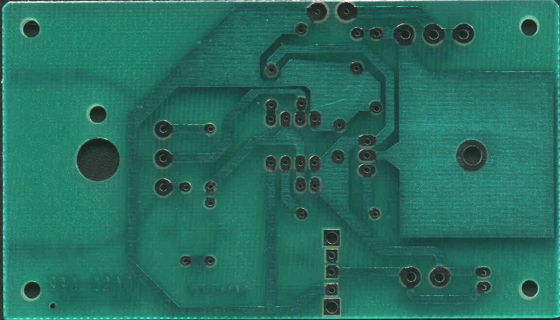
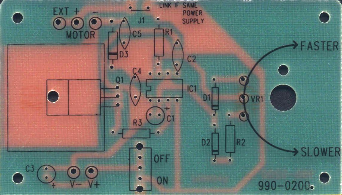
Unpacking the kit, I found an electronics kit geared for the novice. The circuit board is a simple two-sided affair with the circuit traces on the back side and component placement graphics on the front side. Care was given to make sure that the orientation of polarity is clearly marked where necessary. Documentation was outstanding for most of the assembly but a little on the weak side for the mounting of the 555 timer. In case you have never mounted one, the "notch" in the graphic printed on the circuit board (IC1) and the "notch" on both the IC socket and chip all need to line up. Aside from this omission, the instructions were great.
Parts List:
Circuit board:
For those of you who would like to inspect
the board a little more closely, I've scanned the board front and rear.
If you click on the image (to enlarge) and print, they should come out
close to the proper size.
 |
 |
| Description | Value / Item number | Quantity | Circuit |
| Electrolytic Capacitor | 100 µF | 1 | C3 |
| Electrolytic Capacitor | 0.47 µF | 1 | C1 |
| Capacitor | 0.1 µF | 3 | C2, C4, C5 |
| Resistor | 1 k ohms | 3 | R1, R2, R3 |
| Variable Resistor | 10 k ohms | 1 | VR1 |
| Diode | 1N4148 | 2 | D1, D2 |
| Diode | 1N4001 | 1 | D3 |
| Transistor | TIP122 | 1 | Q1 |
| IC | 555 Timer | 1 | IC1 |
Assembly:
This is a pretty easy kit to assemble. You'll need a soldering iron, solder, a few inches of 14 or 16 gauge wire, and some epoxy if you want to mount the circuit board to one of the drive bay blanks. A drill and 9/32" drill bit will help you with mounting the pot to the drive bay blank.
Follow the kit's instructions or the table
above to place the parts. Solder them into the board and clip the
leads. When you get to the point of installing the switch (which
isn't needed for our project) jump a wire between the "on" and "off" connections.
Also jump the connection for the "J1" holes at the top of the board.
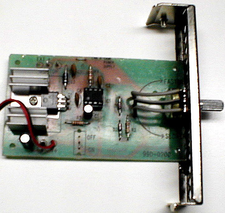 |
To install the potentiometer so that it can be placed on a right angle to the circuit board and stick out through the drive bay blank, I needed to glue (epoxy) the circuit board to the drive bay blank. I then ran wires from the circuit board to the pot. Just make sure that the orientation of the pot is the same as it would be on the board and jump your wires.
Piece of cake, right?
Testing
Though it probably wasn't necessary, I
ran the setup off of my power supply to test it. No problems.
The fan ran fine down to about half its original speed and got much less
loud with the lower RPMs. Perfect.
 |
The only thing left to do was to install
the PWM. I screwed in the drive bay blank and hooked up the power
and fan connections. After booting the box, with the fan set to run
on its highest speed, I turned down the pot until the noise level blended
in with the rest of the computer fans. What a difference!
 |
All in all, a pretty simple project.
The price was right. The results were exactly what I was after.
Slow down the fan enought to take the edge off of the noise and keep the
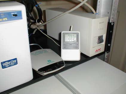
performance to acceptable levels. Temperatures inside the case run
about 2°F higher than room temperature while the computer is at idle
and 3 to 4°F when the system is being stressed.
 |