
|
Over the past few months, I've been testing CPU Cooler Programs, and as the weather has warmed up considerably, a couple of things have become clear. My system (with AMD K6-233 overclocked to 3X83) is not adequately cooled and my method of checking the CPU temperature by measuring the temperature of the heat sink does NOT reflect the processor's actual temperature. I have been toying with some ideas for enhancing the cooling of my Inwin A500 ATX case, but before trying my ideas, I needed a better means of determining my present CPU, heat sink, and case temperatures. Once this was accomplished, I would be better able to gauge the performance of each idea I tested.
Assembling a thermometer
Those of you who are familiar with the
CPU Cooler article may recall that I measured the heat sink's temperature
with a unit assembled from a Radio Shack Temp Module #277-123. While
this set up worked fine for that project, it had one major limitation.
It could not read temperatures over 122° F (50° C). I found
that a couple hours of playing Quake would just about max out the thermometer
(and this was with the case cover off and a large floor fan blowing on
the case). I knew that the processor was getting hotter than the
heat sink's temp probe showed, and that the K6-233's upper temperature
limit is said to be 158° F (70° C). Since I wanted to know
the actualI CPU temperature, I would need a thermometer that was able to
read those higher temperatures. After some reading and deciding on
my requirements (low cost, easy assembly, and reasonable accuracy), I found
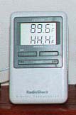
out about another Radio Shack item. This one is listed as an Indoor
/ Outdoor Thermometer Catalog #63-1021. List price was $19.95, but
these go on sale every few months for $14.95. I ended up with two
that I purchased on sale.
This unit is a dual reading thermometer with an internal sensor and external probe. The outdoor probe is a plastic encased thermistor, which is read by circuitry that produces -58° F to 158° F (-50° C to 70° C) readouts with a stated minimum accuracy of ± 2° F. The Indoor sensor is a bare thermistor housed inside the thermometer's case that reads from 32° F to 122° F (0° C to 50° C) with a stated worst case accuracy of ± 2° F. Fortunately, the thermistors have the same values and it is the circuitry that differs. This is a very good thing for my purposes, as you will see.
As with most things that are designed with one purpose in mind and I adapt to another, there were a few obsticles to overcome. The first was my requirement that the probe attach directly to the CPU, not to the heat sink. I have another probe for that purpose. This meant using 1 of 2 methods to attach the probe -- either between the CPU and heatsink or on the bottom of the processor. Since I wanted the probe to be attached close to the center of the CPU, attaching the probe between the sink and the CPU would require a "pocket" to be formed on the underside of the heatsink. I would also have to cut a groove for the probe's lead to exit from between the heat sink and CPU. There were a couple of reasons I chose not to use this method. One, the "pocket" and "groove" would require more machining than I wanted to do, and two, the pocket and groove would lessen the contact area ot the heat sink to the processor. Mounting the probe to the underside of the CPU would only require some method to route the wiring to the outside of the CPU socket. In either case, the thermometer's probe was too large. The thermistor inside the thermometer's case was a good size. It's about a third the size of a grain of rice. By swapping the thermistor with the probe, the size problem would be solved.
 .
. 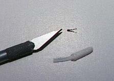
Swapping the thermistor and probe was not difficult. After removing the circuit board from the thermometer, it was a matter of desoldering the thermistor and replacing it with the external probe, keeping about 4" of lead wiring with the probe. I then placed a notch in top of the case so that the probe could extend out of it. Note that some care must be taken to avoid overheating the circuit board and thermistor while soldering. I used a small clip-on heat sink attached to the thermistor's wires.
 .
. 
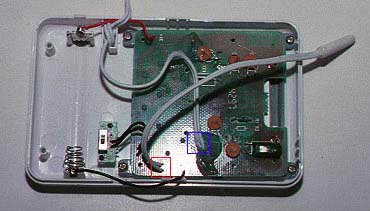
Left: The red box indicates where the
small thermistor was replaced with the external probe.
The blue box shows the outdoor probe's
lead, which is now used for the small thermistor and remains attached.
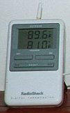
Right: The finished unit with the external
probe showing is now used to read room (indoor) temperature.
To attach the thermistor to the end of the outdoor lead, I used two pieces of 30 AWG (0.01002" - 0.255 mm diameter) solid copper, enamel coated (or some such) wire. The reason for the extremely thin wire was that in order to mount the thermistor to the back surface of the CPU, it would be necessary for the leads to fit between the processor and its socket AND be snaked between the CPU's contact pins. The wire was originally used to wind electric motor armatures, so the insulation was designed to handle heat. Not wanting to take any chances, I baked a piece of the wire in the oven at 250° F for a few hours and checked the insulation for any signs of melting or scorching. No damage was done to the wire, so I'm fairly confident that even if the CPU exceeds AMD's recommended temperature, I will not short out the processor's pins. To allow for easy installation, a small connector was soldered to the ends of the leads and insulated with heat shrink tubing. (Dean's Connector - Tower Hobbies part #LG4738)
With the thermistors swapped, I checked this thermometer against my other thermometers, including a very accurate heating and a/c thermometer. I was amazed to find that all 4 of my electronic units read within a half degree of each other at 80° F and not more than 3 degrees from my calibration unit at high temperatures. All were tested from below freezing to around 150° F. More than satisfied with my results, I moved on to mounting the thermistor to the CPU.
Anyone who has installed a processor in a socket has probably noticed that the center area of the socket is empty. A nice square depression about 1" across. I have long thought that this would be a perfect spot to mount a temperature probe. On an old 486 board I own, there is even a hole cut through the motherboard that could be used to route the probe's wires. Unfortunately, my Abit AX5 has no such hole. In fact, there are circuit traces and small components that prevented me from making a hole of my own. The 30 AWG armature wire is thin enough to fit between the processor and socket. I added a second piece of wire, formed into a loop to allow the processor to sit level in the socket.
Attaching the probe to the back of the CPU presented another question: How to get the best thermal contact while allowing me to remove the thermistor at a later date. Thermally conductive epoxy, while a decent heat conductor, was decided against due to it being a permenent adhesive. After some tests where I found that all I really needed was for the thermistor to be in solid contact with the surface I was trying to test, I chose to use ordinary rubber cement. It has the removal properties I was looking for and didn't weaken or char when exposed to temps in excess of 200° F. All in all, I must admit that while the installation is not the prettiest work I have done, it functions well and the price was right. $15 plus some miscellaneous odds and ends I had laying about.
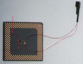
The CPU with probe attached. Note
the Dean's connector at the end of the armature wire.
The arrow points to the piece of wire
used to allow the processor to sit level on the socket.
With the CPU temperature probe installed, I now have 4 different places to read temps -- the CPU, the heat sink, internal case temperature (a probe mounted 1½" off the board near the top of the case), and room temp. This is enough to get me started, but I may have to add more sensors as I progress with this project.
The first reading I was interested in was the difference between the heat sink temp and the CPU temp. I had known that there would be something of a difference, but temperatures I observed were much greater than I had thought they'd be. Previous to being able to monitor the CPU's temperature, I had found that running the demo screen in Quake for a half hour or so would get the heat sink quite warm. The temperature of the heat sink varried with the room temp, but I constantly saw temperatures reaching over 115° F. Here's how the first set of marks looked when I was able to monitor CPU as well as heat sink temperatures.
CPU Cooler heat sink and fan
|
|
°F (°C) |
°F (°C) |
°F (°C) |
°F (°C) |
|
|
|
|
|
|
This test was run with the case cover removed and a CPU Cooler heat sink and fan #MJ 451012, similar to the standard AMD boxed set up for the K6 233. In addition to the CPU and power supply fans, there was a 3½" AC powered fan removing air from the lower front face of the case. The processor is overclocked to 83X3 (250).
With the ambient temperature at 77° F, the processor is less than 11° below the AMD's maximum temp! And I wasn't exactly pushing it that hard, nor was the room that hot. Needless to say, I was more than a little bit concerned. Until this test, I had been fairly confident that when I saw 115° at the heat sink, it was fairly close to the temperature of the processor. Wrong! I guess that I live and learn.
Before I found the temp of the processor to be so high, I had planned on focusing primarily on case cooling, including some tests regarding power supply fans blowing in or out. However, with 3 fans running and the case cover removed and the CPU temp as high as it was, I figured I better address the heat sink first.
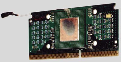
Celeron Update
When I began using the Celeron 300A, I
still wanted to be able to measure the processor temperature. The
layout of the Celeron SEPP made it a little more difficult to mount the
temperature probe. The only place where I could mount the probe in
direct contact with the slug without drilling a hole through the heat sink,
was along the slug's edge. There is not a lot of room, though with
a bit of sanding on the Radio Shack probe to flatten it out a bit, it fits
nicely between the circuit card and the heat sink.
Again, the rubber cement used on the K6 proved to be a good choice. Removing the probe from the K6 was an easy task and after a quick clean up and applying a bit more rubber cement, it was mounted securly to the edge of the Celeron slug.
While it is true that mounting the thermistor in the center of the slug would probably give a little more accurate reading, drilling a hole through the heat sink to mount the probe would lessen the contact area of the heat sink to slug.
Top - Probe in place at the edge of
the slug.
After cementing the probe's wires in
place, the thermistor was held against the edge of the slug and a
drop of rubber cement was placed over
the top of the thermistor and held firmly until the cement dried.
|
|
|
|
|