
|

Of course, 527 wasn't enough. I wanted a processor with a higher multiplier that I could hopefully push a little farther. I had been thinking about going with a PPGA packaged Celeron, but I still had some ideas for a water cooler for a slot one type to try out and I still hadn't come up with a way to clamp a thick heat sink to the PPGA socket. I ended getting a OEM 366 slot one.
The idea behind Water Cooler 2 was to run
dual 40 mm TECs on a cooler that could be assembled without the massive
amount of labor that the copper base with aluminum pins took. This
time I would try machining a copper sink on my drill press. A drill
press is not really designed to take the lateral forces that are applied
in machining and they tend to be a little sloppy with side to side movement.
I spent some time working on the drill press's bearing and rack housings
to shim them up a bit and remove the slop. I was pretty successful.
|
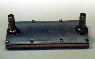
The sink was designed to maximize the amount
of surface area the water would contact in the shortest period of time.
The copper base is 3/8" thick by 5" by 2". The top plate is 1/8"
aluminum with a fiber gasket between the two. The inlets are standard
plumbing parts.
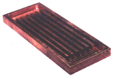
off to help lessen resistance to the water's flow. |
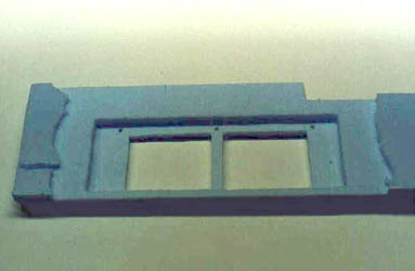
I was somewhat surprised at how "hard"
copper is, compared to aluminum. I could only remove a few hundredths
of an inch of material with each pass. This meant that the
channels took quite a while to machine down to their 1/4" depth.
|
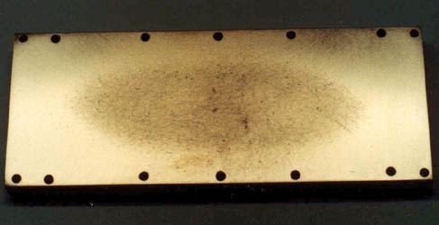
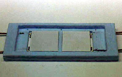
With the passages cut and the holes drilled,
I set about getting the bottom of the base flat enough to make good contact
with the peltiers. With the drill press not accurate enough to machine
the surface to the tolerance I was after, it was back to the lapping table.
If you think it takes time to lap the Celeron's slug flat, try lapping
something 10 times it's size. You can see that no matter how tight
I taped down the sandpaper, and how carefully I lapped, a certain amount
of rounding occurs on the corners. Fortunately, this is in an area
that will not contact anything.
|
1/2" in height. |
With the basic heat sink assembled, it
was time to start on the cold plate and the insulation. So far, the
time involved in building this prototype was a little less than half the
time I had spent on getting Water Cooler 1 to this point. A definite
improvement.
|
The first piece of insulation was to go
between the sink and the cold plate to hold the to 40 mm TECs. Starting
with some 5/8" foam insulation from the local home center, I machined up
the insert. Boy, I wish metal machined as easily as the foam!
|
On Water Cooler 1, I found out how important
it was to get a good fit for the insulation. The closer the fit,
the less air that can make contact with the cold surfaces. This is
a great help in reducing the amount of condensation that the sink produces.
|
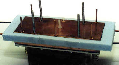
With a small amount of good quality thermal
paste between the parts, the sink and peltiers were assembled. The insulation
was added, then more thermal compound and then the cold plate. Of
course, there was a good amount of time spent lapping both sides of the
cold plate before it was ready to assemble. The four holes in the
center of the cold plate were not drilled all of the way through so the
studs would not hit the peltiers. The six holes on the edges of the
plate were drilled and countersunk so that the nylon 4-40 screws would
sit flush. Nylon screws were used to try to limit heat transfer between
the sink and the cold plate.