
|
Having reached the point where I have thermometers to check temperatures and a large enough heat sink and fan combination to prevent cooking my CPU in most situations I'll probably encounter, it's time to turn my attention to the main reason I assembled this equipment -- case cooling. I started off thinking of extreme and exotic methods to cool the processor and components enough to allow me to try for 3.5X83 out of my AMD K6-233. While I still may try out some ideas I have for fluid cooling and will most definitely try playing with some peltiers, I have become more interested in cooling for cooling's sake, rather than as a means to overclock beyond the 250 MHz I am presently running at.
The learning process I have gone through -- and am still going through -- has taught me that there is much more to case cooling than having plenty of fans. I have put this article together in the order that I made each change to the system to show the effect that each change had on the system's overall cooling performance.
ATX Case Power Supply Fan
The general consensus on the various bulletin
boards I frequent would seem to suggest that the designers of ATX power
supplies designed them with the fans running backwards. The standard
ATX power supply fan brings in air from the room and passes it through
a hot power supply and then exhausts it into the computer case. The
power supply of most ATX cases is located near the top of the case.
In my Inwin A500, this means that the warm air from the power supply is
being directed very close to the CPU's heat sink. While the air coming
from the power supply is cooler than the heat sink, it is warmer than air
taken directly from the room. Exhausting the heated air in the case
was left to some vents cut along the case cover's sides, rear, and the
grill located in the lower front of the case's face plate. This arrangement
requires the heated air to travel downward to escape from the case.
As an option, a 3" fan can be located in the lower front of the case to
assist in exhausting the case's warm air. As many people have pointed
out, this arrangement would seem to be exactly backwards of the "hot air
rises" rule.
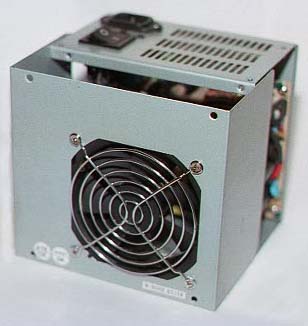
One solution that many people have gone to is to replace the power supply with one that has a fan that "exhausts" rather than "intakes" air. As I already had the stock power supply, I decided to see how difficult it would be to reverse the direction of the air flow of the one I had. As it turned out, this was an easy 20-minute task that was performed with nothing more than a phillips screwdriver. After performing this minor surgery on my power supply, I have done the same to 6 other brands of supplies with equal ease and success.
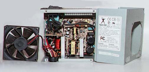
Flipping the Fan Over
First, unplug it! -- both from
the wall socket and from the board. Mark any connectors that will
help you reinstall the plugs to their respective connections. Remove
the power supply from the case. In the 7 supplies I tried, this was
a matter of unscrewing 4 phillips screws from the rear of the case and
lifting the supply out. Remove the cover of the power supply (4 to
8 screws) being careful not to touch any of the power supply's electrical
components or wiring. The power supply may still retain enough stored
current to give you one heck of a jolt. On 6 out of 7 of the power
supplies the next step was to remove the 4 screws that attach the wire
grill to the P/S housing and fan. Flip the fan over so that the sticker
on the fan blade's hub faces the opposite direction and reassemble.
The seventh power supply had the fan held in by small metal clips instead
of screws, but the process was much the same.
 |
 |
Now that the fan is exhausting, remember that if you have a second fan in the front of the case, you will need to flip it over as well. Now you should have a system that draws the relatively cool air of the room in through the lower front of the case and exhausts through the power supply (located somewhere higher in the case).
OK, in theory this should make for a cooler case. I ran some before-and-after tests to check how much of a difference swapping the direction of flow actually made. The tests were made running Rain and letting the case, heat sink, and processor temperatures reach their lowest possible point (about a half hour with the system idle). These temperatures were recorded. I then ran the Quake demo screen for a half hour and recorded the temperature. This was done for both air flow directions with the case cover on and off. Note that the starting temperatures are not exactly the same. They are as close as I could get them with the varying temperatures in my computer room. Each test was run 6 times over the course of a few days and the temperatures were averaged. The reason for the "case cover off" tests is that this is the way the system has been run for the past 6 months. (I had to keep it cool somehow.) My goal is to come as close as I can to the temperatures I get with the case cover off while keeping the case cover on.
System
AMD K6-233 o/c'd to 3X83
Abit Ax5 mainboard
Inwin A500 mid tower ATX case with Power
Man 235 watt power supply.
4 1/2" 110 volt front fan - mounted flush
against the case.
Win95 OSR2.5
Rain, version 1.0 - cooler program
.
Temperatures - P/S fan blowing In / Out
| Configuration |
|
|
|
|
| P/S fan blowing in
case cover on -- at Idle |
|
|
|
|
| P/S fan blowing in
case cover on -- Quake |
|
|
|
|
| P/S fan blowing in
case cover off -- at Idle |
|
|
|
|
| P/S fan blowing in
case cover off -- Quake |
|
|
|
|
| P/S fan blowing out
case cover on -- at Idle |
|
|
|
|
| P/S fan blowing out
case cover on -- Quake |
|
|
|
|
| P/S fan blowing out
case cover off -- at Idle |
|
|
|
|
| P/S fan blowing out
case cover off -- Quake |
|
|
|
|
If you match the blue numbers for the P/S fan blowing in and out, you'll see that there is not that much of a temperature difference with the system idle. The purple numbers (with Quake running) show a different story. With the power supply fan exhausting and the front fan working as an intake, there is almost a 4° drop in the CPU temperature from the stock configuration with the case cover in place.
Restricted Air Flow?
When I first assembled my system, I added
a 3" fan to the Inwin-supplied holder in the lower front of the case.
This was a standard 12 volt fan, much the same as can be found in the power
supply. Inwin supplied a nice plastic housing that the fan slipped
into. As time went on and I started overclocking, I replaced this
fan with a 4 1/2" 110 volt fan. This meant that I could no longer
use the Inwin-supplied holder. I ended up attaching the fan directly
to the grill, which is no more than an array of holes punched in the case's
metal frame. This allowed the fan to draw only outside air and not
recirculate the warm air in the case. A good solution, I thought.
The only drawback I could see to this setup was that the metal fan housing
against the metal case frame tended to transmit a fair amount of noise.
I had planned to eventually place a rubber gasket between the two to quiet
it down..
. .
.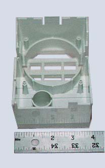
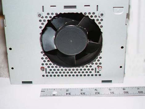
Left: The 4 1/2" 120 vac front fan
and front case grill.
Right: The fan holder shows how Inwin
solves the air
flow blockage problem by increasing
the size of the duct
to compensate for the reduced intake
area of the grill.
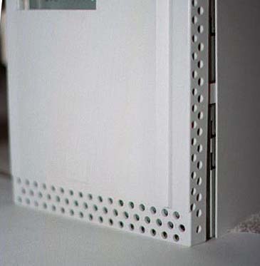
Over the next week or so, I designed and built a half dozen fan ducts. After testing each of these I found that while they did greatly increase the amount of air flow that the fan produced, the fan ended up too far back in the mid tower case for the air to travel easily to the area of the CPU's heat sink. I finally decided that for my purposes, the best way to solve the air flow problem was to remove the grill that was blocking the air flow and mount the fan in the same place I had originally placed it. So much for keeping the case in its stock configuration!.
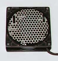
The grill blocked quite a bit of the
fan blade
opening when mounted flush with
the case.
With the 4 1/2" fan mounted unobstructed in the front of the case and the front plastic case cover removed, the fan brings in so much air into the case that the case becomes positively pressurized. Air can be felt escaping from every crack and open seam in the case. The air that is being forced into the case also causes the power supply fan to speed up slightly and exhaust more air than it could without being "force fed." At this point I wasn't sure that this was exactly what I wanted, thinking a "free flowing" air exchange (where the case exhausted as much air as it took in) would allow for more air to be replaced in the case in the same period of time. But whatever I finally decided on, it was time to check the temperatures again..
The front fan is installed.
| Configuration |
|
|
|
|
| Front fan restricted
case cover on -- at Idle |
|
|
|
|
| Front fan restricted
case cover on -- Quake |
|
|
|
|
| Front fan restricted
case cover off -- at Idle |
|
|
|
|
| Front fan restricted
case cover off -- Quake |
|
|
|
|
| Front fan not restricted
case cover on -- at Idle |
|
|
|
|
| Front fan not restricted
case cover on -- Quake |
|
|
|
|
| Front fan not restricted
case cover off -- at Idle |
|
|
|
|
| Front fan not restricted
case cover off -- Quake |
|
|
|
|
At the end of this test, it was beginning to look like I was making some real progress. I was, but the last set of tests were run with no front cover on the computer. As I expected, as soon as I reinstalled the front case cover, the air flow decreased and the temperatures rose again. Not as high as they had been with the fan mounted flush against the restrictive grill, but not as low as they were with the front cover off.
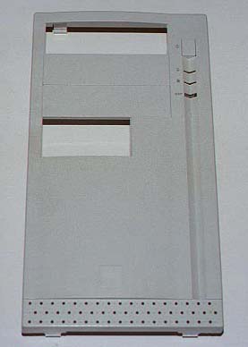
Holes in the Face Plate
With the goal of increasing the air available
to the front fan, I knew that I needed a total of (at least) 15.9 square
inches of openings (holes) to equal the 4.5" blade opening of the front
fan. (4.5/2)(4.5/2)(3.14) I first tried removing a couple of the
plastic dummy CD and floppy face plates and watching the temperature readings
for the case. While I now had a large enough opening to draw air
in through, the case temperature was not as low as it was with the front
cover removed. Since the front cover already came with 50-some 3/16"
holes drilled at the bottom of it, I could gain a few square inches by
drilling the holes out to 1/4". The
oversized holes added to the openings already created by removing the drive
blanks brought the temperature down another 1/2 of a degree, but still
not low enough..
 .
. .
.
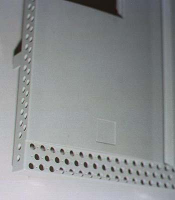
Enlarging the existing holes and adding
some more.
Left: Stock Right 2: Modified
Since cutting holes in the front cover is something that I can't undo, I made some mock-ups out of cardboard and tried cutting holes around the perimeter of my test covers. After playing with a couple of the mock-ups, I received favorable enough results to start drilling on the case cover. To make a long story short, I have not been able to get the case temperature to drop below what it is with no cover installed in all situations, but I have come within about .2° at idle and a degree or two with the Quake demo screen running. I have drilled about 60 1/4" holes along the sides of my front face plate. Since I was planning on adding one more fan and figured that the flow properties would change with the new addition, I stopped drilling holes about 1/2 way up the sides of the cover. I can always add more if they are needed.
If you're wondering why partially obstructing the fan is improving the cooling performance, join the club. I'm wondering too. After discussing it with a few people, a couple of ideas have been accepted as possibilities.
First, it is possible that the fan is intaking too much air and bypassing the "chimney" between the drives in the front of the box and the cards in the rear of the box. At the top of this "chimney" (empty space that runs vertically in the center of the box) is the processor and heat sink. It is also where the case temperature sensor resides. By partially blocking the fan, I could be slowing down the air flow enough to allow it to travel up the chimney.
Another idea is that the fan's center hub (which is large and flat) is causing some turbulence that is lessened by making the fan draw its air form the sides.
At some point I'd like to make a clear lexan side cover for the box and with the help of some smoke, try to "see" what is happening to the air flow. For now, I'll just accept the fact that my box seems to like the intake air to come from the sides of the front fan, rather than straight in.
Top Fan
The very top of my case had no assisted
way to get rid of the heat that builds up there. There are a few
rows of holes at the top rear of the case that do exhaust some heat, but
I wanted a way to scavenge the heat and remove it quickly. After
considering a conventional fan mounted to the rear of the case, I decided
to try a blower that I have heard nothing but good things about.
This is a "squirrel cage" 12 volt blower sold by Radio Shack (part # 273-260
- Brushless DC Blower). There were 3 good reasons for the choice.
The blower intake is at a right angle to the exhaust, which would allow
me to scavenge hot air from a inch or so of the case top and direct it
out the rear of the case. It moves quite a bit of air for its size,
and it's quiet. Very quiet..
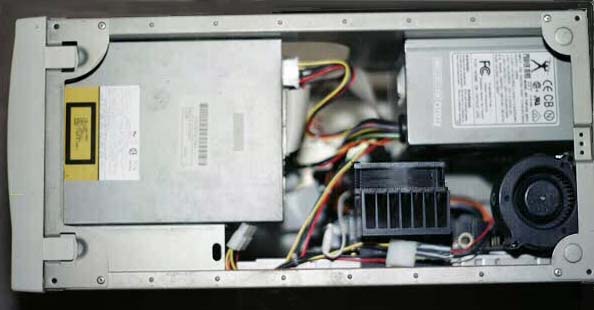
The "squirrel cage" mounted to exhaust
out the rear
of the case.
As you might expect, the installation of removal of a component or card also changes the air flow in the case. With a bit of duct tape, some cardboard, and a lot of time, it is possible to "tune" the air flow for each component that is installed or removed from the box.
The table below is the same format as before with the top 4 rows reflecting the setup and temperatures from the bottom 4 rows of the last table and the bottom 4 rows of this table reflecting the changes that adding the drilled front cover and additional exhaust fan made.
Temperatures - Front Cover Modified and Top Fan Installed
| Configuration |
|
|
|
|
| Front fan not restricted
case cover on -- at Idle no front cover |
|
|
|
|
| Front fan not restricted
case cover on -- Quake no front cover |
|
|
|
|
| Front fan not restricted
case cover off -- at Idle no front cover |
|
|
|
|
| Front fan not restricted
case cover off -- Quake no front cover |
|
|
|
|
| Case cover on -- at Idle
new front cover & fan |
|
|
|
|
| Case cover on -- Quake
new front cover & fan |
|
|
|
|
| Case cover off -- at Idle
new front cover & fan |
|
|
|
|
| Case cover off -- Quake
new front cover & fan |
|
|
|
|
| Configuration |
|
|
|
|
| CPU Cooler heat sink
case cover on -- at Idle P/S fan on intake |
|
|
|
|
| CPU Cooler heat sink
case cover on -- Quake P/S fan on intake |
|
|
|
|
| After modifications
case cover on -- at Idle P/S fan on exhaust |
|
|
|
|
| After modifications
case cover on -- Quake P/S fan on exhaust |
|
|
|
|
| Configuration |
|
|
|
|
| Difference in idle
temperature decrease |
|
|
|
|
| Difference in Quake
temperature decrease |
|
|
|
|
Final Thoughts
The addition of the very large heat sink
did the most to lower the CPU's temperature. Switching the flow of
the power supply and lower fan proved to be effective in getting rid of
some of the case's heat, though it wasn't until the addition of the top
fan that I was able to stop the top of the case cover (right above the
heat sink) from being warm to the touch while running Quake. Removing
the restriction from the front case fan had a dramatic effect on the amount
of air I was able to exchange.
All things considered, the project went pretty well. I would have preferred not to have had to cut the case and front face plate, but I didn't see a viable alternative. If I had to do it over again, I would have started with a full tower case. I believe that the extra air space would have made cooling this system much easier. (Next system!)
Now that I have reached the point that I have a very large heat sink and am able to exchange the air in the case quickly, I am ready to take the next step. I'm thinking along the lines of a peltier installed between the processor and heat sink. It also might be nice to have the peltier temperature controlled, running only when needed, to minimize the condensation problems commonly encountered while running the CPU much colder than the ambient air temperature.
Thanks to Charlie, DanHu, and Steve for
their help with answering the multitude of questions I had and continue
to have.
|
|
|
|
|