
|
 |
I seem to have this thing for flashlights and thermometers (as if you couldn't tell about the thermometers). The flashlight thing is a whole different story, but suffice it to say that I have more than a modest collection (including my present favorite, a big, xenon-bulbed MagLite rechargeable that clamps into the charger mounted in my 4X4). But I digress... this article is about thermometers and how to build a moderately accurate one that will log temps to your computer using very few parts and some software I wrote for the occasion.
This project started with the need for an additional thermometer - preferably a 4 channel unit that would log data directly to my computer. I looked at quite a few and found that I could pick up a 2 channel, type "T" thermocouple logger for about US$ 160 (Extech Model 421508 http://www.qualityinstrumentsinc.com/products/extech/tt.html). It looks like a nice unit and would be more practical than my Omega HH22 in that I could log the temps directly to a computer, rather than furiously scribbling numbers every few seconds as I try to plot my temperature charts. I also found a couple of really nice 8 channel loggers, but I could have built another computer for the price they wanted.
About the same time I was looking into
these, I ran across a site where a guy had done a mod on a thermometer
that interfaced the computer via the game port. Bunker
Mentality's article on the ComputerNerd ALSI thermometer details how
to swap and modify the thermistors on this setup. I was intrigued
enough to look into this sale item from the ComputerNerd
bargain corner. For $2.75, I knew I'd be hard pressed to
get just a quality 15 pin "sub D" connector, much less the included "Y"
adapter, circuit board, and 100k ohm thermistor, so I ordered a few.
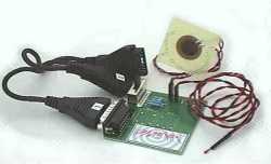 |
After a couple days wait, I had four of the units. (Yes, I said four.) Contrary to the picture on their site, my ALSI temp monitors only came with one 100k ohm thermistor set into a socket 7 adapter, rather than the two sensors shown, but it was still a good deal. I was somewhat surprised when I looked at the circuit board. There wasn't much in the way of components. A switch, 4 resistors, two - 2 pin connectors and the 15 pin "sub D" connector. But hey, what do you want for $2.75 - except that it seems to have sold for $40 when introduced. Upon looking into how the circuit worked, I found that the gameport will read the sensors directly. The 4 resistors on the ALSI unit are just for calibration. Of course, this got me to thinking that I could build one of these pretty easily.
The game port interface is pretty simple
as computer ports go. Data is input only and the port functions as
an analog to digital interface. The original PC joysticks were analog
and were made up of two switches that served as fire buttons and two potentiometers
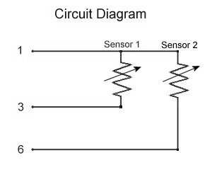
(pots). One pot for each axis (X and Y). The pots used
are a linear type with a typical value of 100 k ohms and serve to vary
the voltage received from the power source (pin 1) and return it to the
inputs (pins 3 and 6). The pots (or thermistors) are wired as shown below.
 |
 |
| Pin | Use | Joystick A or B |
| 1 | +5 Volts | 5 Vdc |
| 2 | Fire Button 1 | A |
| 3 | X axis potentiometer | A |
| 4 | Ground | Ground |
| 5 | Ground | Ground |
| 6 | Y axis potentiometer | A |
| 7 | Fire Button 2 | A |
| 8 | +5 Volts | 5 Vdc |
| 9 | +5 Volts | 5 Vdc |
| 10 | Fire Button 1 | B |
| 11 | X axis potentiometer | B |
| 12 | Ground / MIDI | MIDI |
| 13 | Y axis potentiometer | B |
| 14 | Fire Button 2 | B |
| 15 | +5 Volts / MIDI | MIDI |
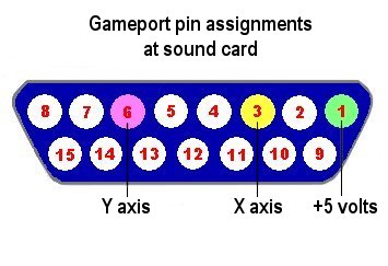
The circuitry connected to the game port (the sound card for most recent applications) does an analog to digital conversion on the voltage for each axis and the software reads it as a value. The value is 0 for 0 Volts and 65535 for 5 Volts. In turn, the software assigns that value to move your player up and down (Y axis) or left and right (x axis) - or a combination of the two. Later in their evolution (in the early 80's), joysticks switched from analog to digital. These joysticks replaced the pots with digital (on/off) switches.
Thermistors vary their resistance when their temperature is changed, although they are not linear like the pots used in a joystick. The coefficient of resistance ratio between the resistance and temperature (the Alpha) changes across the temperature / resistance range. For example, a thermistor with an Alpha of -4.4% / °C at 25°C could have an Alpha of -3.8% / °C at 50°C. The plotting of thermistor temperature-resistance relationships are standardized into what are known as resistance / temperature (R/T) curve tables. The R/T curve works with the equation T = RT / R25. The notation R25 is the resistance of the thermistor at 25°C and RT is the resistance at the temperature you are trying to discover. To determine the nominal resistance value of a thermistor at a specified temperature, you multiply its resistance at 25°C (R25) by the corresponding RT value for the desired temperature from the table that corresponds to the resistor you are using. The material composition of the thermistor dictates which table is used. An example of a thermistor curve table may be found here. If you're into working the math yourself, this page should help with the many considerations necessary to accurately plot the thermistor curve. Ocean researchers Steinhart and Hart proposed fitting the standard curve with RT as a polynomial in the equation 1/T = a + b[lnRT ] + c[lnRT ]2 + d[lnRT ]3. This equation is very accurate in plotting the thermistor curve and is the basis for calculations in the gp_Temp program.
One of the problems of using the gameport as a thermistor interface is that the gameport only reads values from 0 to 65535, while the thermistor curve assumes infinite ohms. Fitting an infinite number into 65535 is a tight squeeze at best. The game port also does not read each individual number between 0 and 65535, but reads by intervals - as in 088, 188, 288, etc. This is fine at room temperature where 1°F may have a gameport numerical value range of 4000 (you could easily read temps accurately to 1/10 of a degree or better), but is a problem at the high and low temperatures where 1°F may only be represented by a span of 40. This means that the useable range for a 100 k thermistor with 1°F resolution comes out to be about 46°F (7.7°C) to 171°F (77°C) on my system. While the range for a 100 k thermistor is fine for measuring the temperature of an air cooled heat sink, it doesn't cut it for my water cooled, peltier assisted coolers where the cold side of the peltier goes sub-freezing. By using different values of thermistors, the gameport will read different temperature ranges. The following ranges are read by my system:
10 k ohm thermistors can register a range
of -40°C to 25°C (-41°F to 77°F).
50 k ohm thermistors can register a range
of -3°C to 65°C (26°F to 150°F).
100 k ohm thermistors can register a range
of 7°C to 77°C (46°F 171°F).
While using different thermistors to read different ranges is not the ideal solution, it is a solution that works for my present applications. I can use a 10 k thermistor to monitor the cold side of the peltier and a 50 or 100 k thermistor to measure the water temperature coming from the water block.
To get this thermometer up and running,
you can either pick up one of the ALSI units and try both the software
that comes with it and my gp_Temp software or assemble your own hardware
from scratch for a few bucks and run my free software. If you go
for the ALSI unit, which is a pretty great deal, the setup is outlined
in the instruction page that comes with the unit. You can also take
a look at Bunker
Mentality's installation page, which gives an accurate description
of the software load and calibration process. I won't rehash this,
but it is very important that when setting up the Windows game port that
the 2 axis, 2 button joystick controller is chosen and that the port driver
is listed as Standard. Failure to use either will cause the program
to either not read at all or read incorrect values. After a little
futzing around, I got the ALSI program working. It does do what it
said it would do - measure temperatures - though not with the greatest
degree of accuracy, even if you take into account the fact that the game
port interface is not the best for the purpose of measuring temperatures.
I would guess that the less than stellar accuracy of the ALSI software
is the result of the fact that there is a fairly loose tolerance between
thermistors unless you use what are known as precision or interchangeable
thermistors and that the calibration process does not account for this.
I have observed more than 4°F difference between "identical" thermistors
at room temperature. Though the calibration process for my program
is certainly not as easy as with the ALSI software, I think is is more
accurate.
OK, enough of the background. Let's build this thermometer.
|
page 1 |
page 2 |
page 3 |
page 1 |
page 1 |
page 2 |
page 3 |