Adding Temp Monitoring to the
1800T
Click on smaller images to enlarge.
 Since
I now had the 1800T up and running a dual boot of redhat and Win2k, what
was there to do except take the thing apart. From looking at the
Compaq PDF on connector pin outputs, it appeared that the docking station
connector would have all of the connections I needed to grab the gameport
circuitry and hook in my temperature sensors. All I would need to
do is take the 1800T apart and do a little soldering. Well, I was
partially right.... Since
I now had the 1800T up and running a dual boot of redhat and Win2k, what
was there to do except take the thing apart. From looking at the
Compaq PDF on connector pin outputs, it appeared that the docking station
connector would have all of the connections I needed to grab the gameport
circuitry and hook in my temperature sensors. All I would need to
do is take the 1800T apart and do a little soldering. Well, I was
partially right....
To get started, I purchased a nice set
of Torx screwdrivers. All I had in Torx were a bit on the worn side
and I wanted to make sure that my new laptop still looked new after this
ordeal. The tools required for disassembly are minimal. A T8
Torx driver, a Phillips driver - I used a #0, a flat bladed screwdriver
- again a small one, a 5 mm nutdriver or socket and some patience.
Be advised that the laptop's case is what we in the auto industry used
to call "precision plastic." "Precision" was used as a joke to describe
parts that either didn't fit together well or fit together in such a way
as they wouldn't come back apart. In the case of the Compaq, the case fits
together well. Almost too well. Some gentle persuasion is required
to get the pieces apart. The PDF is pretty clear on the order of
disassembly and which way to "force" the pieces apart, but you need to
exercise a certain amount of restraint in how much pressure you use.
I printed the PDF file for easy reference.
I also read through the entire procedure a few times to try to familiarize
myself with the steps and made notes on things that weren't clear to me.
Better to be aware of the areas that I thought that I might have problems.
To keep from scratching the surfaces, I
worked on a towel. I also set up another towel where I could place
the items I removed from the computer in the order that they were removed.
This may seem like overkill, but I tend to get interrupted by one thing
or another and I wanted to be darn sure that I knew where everything went.
Nothing in this process is that dificult,
with the possible exception of soldering to the tiny "legs" on the motherboard.
However, if you have to question yourself whether you should be attempting
this project, you probably shouldn't. |
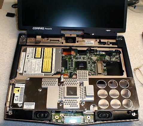
The takedown begins
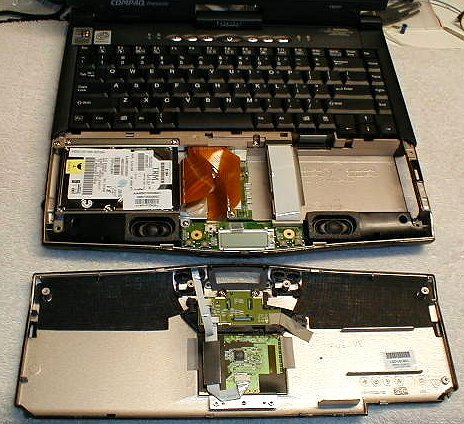 The
disassembly started with the removal of the battery and removing the first
5 T8 screws (4 long and 1 short) from the bottom of the case. Flip
the case back to right side up and slide your fingernails into the center
of the seam that runs horizontally along the front of the case. Lift
upward and toward yourself until you hear the first "pop" of the plastic
retainer catches coming loose. The pop that the plastic makes when
it releases is guaranteed to send a chill down your spine, no matter how
many times you have heard it before! Move your nails an inch or so
away from the center and repeat lifting. Repeat until the top cover
comes loose. Disconnect the ribbon cable from the bottom half of
the case and lift off the top cover. The
disassembly started with the removal of the battery and removing the first
5 T8 screws (4 long and 1 short) from the bottom of the case. Flip
the case back to right side up and slide your fingernails into the center
of the seam that runs horizontally along the front of the case. Lift
upward and toward yourself until you hear the first "pop" of the plastic
retainer catches coming loose. The pop that the plastic makes when
it releases is guaranteed to send a chill down your spine, no matter how
many times you have heard it before! Move your nails an inch or so
away from the center and repeat lifting. Repeat until the top cover
comes loose. Disconnect the ribbon cable from the bottom half of
the case and lift off the top cover.
In the first few sections of the disassembly
PDF, there are some pages on the connectors used in this laptop.
These are pretty standard fare, but much different than what you're used
to if you've only dealt with desktop systems. The connectors are
female only with the male side being just the ribbon cable itself.
The exceptions to this are the connector for the flat panel screen, which
has both a male and female connector and the power connectors which use
standard wire. It is advisable to pay close attention to the instructions
on how the connectors come apart before you start yanking on things.
I won't go into as much detail for the
rest of the disassembly, but the first step can make or break you.
Literally. This cover was tight on my laptop and I was fearful of
breaking something. Once I was able to get a look at how the plastic
latches worked, the next time I took it apart it was easier. (Next time?
Yes, this was the first of MANY times I have had this box apart.) |
That's a heat sink?
 Once
the touchpad cover has been removed, the keyboard lifts out. There
are no screws holding it. Lift it up a little bit and you'll see
the connector on the right. Unplug it and the keyboard lifts out
- up and toward you. Once
the touchpad cover has been removed, the keyboard lifts out. There
are no screws holding it. Lift it up a little bit and you'll see
the connector on the right. Unplug it and the keyboard lifts out
- up and toward you.
Once the keyboard is out of the way, you'll
be looking at a flat piece of sheet metal with six T8 screws (2 long and
4 short). This is the support for the keyboard and the hold down
bracket for the heat sink. The 4 screws in the center clamp the heat
sink to the processor. The two additional screws locate the
assembly on the motherboard.
In hindsight, it would probably be best
to work on the 4 center screws first. Loosen them a bit at a time
in a circular fashion so as to take the tension off the processor evenly.
Once you have these out, remove the two remaining screws. |
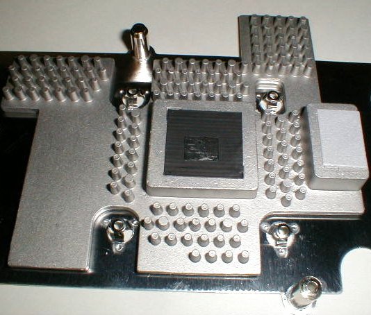 Why
the care in removing the 4 screws? Because like many manufacturers,
Compaq chose to use a rather rough heat sink casting and took care of "making
it flat" by using thermal tape. This thermal tape compresses and
does a pretty good job of filling in any voids in the rough casting; however,
it does not like to be reused. Being very gentle with the removal
of the heat sink may give you a better shot at reusing the tape.
I had the sink - with tape - on and off a few times without noticeably
damaging it, but I knew I would be stripping it off in favor of a better
interface before the project was through. You may opt to keep your
tape intact. Why
the care in removing the 4 screws? Because like many manufacturers,
Compaq chose to use a rather rough heat sink casting and took care of "making
it flat" by using thermal tape. This thermal tape compresses and
does a pretty good job of filling in any voids in the rough casting; however,
it does not like to be reused. Being very gentle with the removal
of the heat sink may give you a better shot at reusing the tape.
I had the sink - with tape - on and off a few times without noticeably
damaging it, but I knew I would be stripping it off in favor of a better
interface before the project was through. You may opt to keep your
tape intact.
Notice the 4 raised areas of the sheet
metal. These are where the short screws attach to hold the sink to
the processor. The 4 raised areas actually act like springs to even
out the clamping pressure on the processor. These can be pushed down
a bit (made flatter) to increase the tension on the sink to processor bond.
To the right of the square pedestal that
mates to the processor is a rectangular casting that has some white foam
on it. This hump sits atop of a chip on the motherboard. I
would have guessed that thermal tape would be used here to help dissipate
the heat from the chipset, but if this is thermal tape, it is unlike any
that I have seen (and I have seen a few types...). It just appears
to be foam to help support the casting. Whatever, it will get thermal
tape before I am through :-).
One last comment (for now) on the sink.
I am a bit bummed that I didn't end up with a laptop with some tricked
out heat pipe assembly on it. Yes, I know that they're more expensive
to produce, but with my interest in heat pipes, it would been fun.
This heat sink is, well, kind of boring.... |
Getting down to the basics
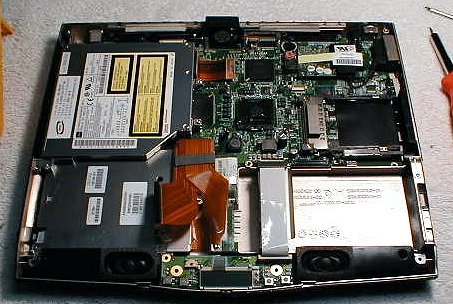 I'll
stop with the blow-by-blow account of the disassembly, as the rest of the
process is pretty straight forward. According to the instructions
from Compaq, here's the whole procedure with page numbers. I'll
stop with the blow-by-blow account of the disassembly, as the rest of the
process is pretty straight forward. According to the instructions
from Compaq, here's the whole procedure with page numbers.
1. Prepare the Notebook for disassembly
(pg 10).
2. Remove the Palmrest cover with
TouchPad (pg 13).
3. Remove the keyboard (pg 16).
4. Remove the heat sink (pg 23).
5. Remove the button board cover
(pg 17).
6. Remove the Internet switch board
(pg 21).
7. Remove the display panel assembly
(pg 34).
8. Remove the hard drive (pg 25).
9. Remove the upper CPU cover (pg
37).
10. Disconnect the LCD DisqPlay module
cable from the system board (pg 28).
11. Remove the modem (pg 24).
12. Remove the CD, CD-RW, or DVD drive
(pg 31).
13. Remove the fan assembly (pg 38).
14. Disconnect the diskette drive cable
from the system board (pg 43).
15. Remove the voltage converter board
(pg 44).
16. Disconnect the speaker assembly cables
from the system board (pg 46).
17. Remove the system board (pg 47).
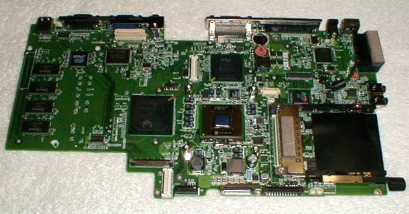 Page
51 tells you to "Make sure that the PC card eject button is pushed inward,
and then lift up the front of the system board and pull it forward to remove
it from the chassis." Page
51 tells you to "Make sure that the PC card eject button is pushed inward,
and then lift up the front of the system board and pull it forward to remove
it from the chassis."
This procedure is a little more tricky
than the text would have you believe. On the under side of the mainboard,
in the rear (toward the port connectors), there are obstructions.
One is a bent piece of spring metal that acts as a "ground strap."
There are also a couple of plastic pedestals that serve as receptacles
for screws. The motherboard tends to get hung on all of these.
Moving the board slightly to the left before lifting the front edge helps,
but I found that patience and a lot of wiggling and gentle persuasion were
needed to release the board from these demons.
I've had the board out a few times and
the task didn't get any easier with practice. Walk away from it if
you get frustrated. It will come out... eventually. |
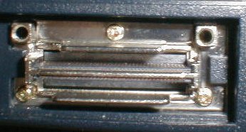
Getting at the connector
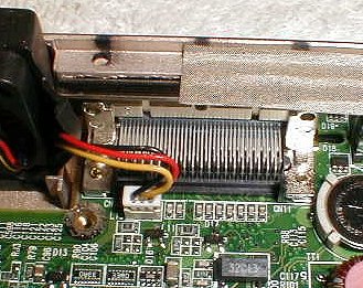
| At the step when I had the heat sink removed,
I realized that my original hope of soldering directly to the docking station
connector pins was over. The pins I needed were hidden below the
first (accessible) layer of pins. My only chance for getting access to
the pins was on the bottom of the motherboard, but that the board would
have to come out.
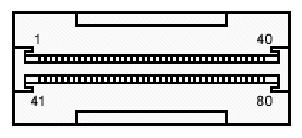
The connector is an 80 pin unit with everything
from video signals to (obviously) the gameport running through it.
It is also pretty small. Small enough that it is hard to get a reading
off of an individual connector trace from the rear of the laptop with my
digital multimeter. Soldering to the legs of the connector on the
bottom of the motherboard was going to be a trick.
|
|