HOME
What's New

CPU Cooler
Programs
Introduction
AmnHLT
CpuIdle
Rain 
VCool 2.0 
Waterfall Pro 
Current Tests 
Test Archives

UDMA Driver 
Tests 
Windows 95
Windows 98
Windows NT

Way 2 Cool 
Projects 
Compaq 1800T
1800T Temp Monitor
Celeron-A
Going for 504
More on 504
Cheap Sandwich
BX6r2 Diode Fix
Condensation
Lap that Slug
Celeron PPGA
Journey to 1080
Building an NT Box
Heat Pipe 1
Heat Pipe 2
Heat Pipe 2.2
gp_Temp
gp_Temp4
gp_Temp5

Heat Sinks 
Aavid
A&C Prototype Sink
Alpha P125
Alpha P521
CPU Cooler
FullWay
Tom's Sink
Water Cooler 1
Water Cooler 2
Water Cooler 3
Water Cooler 4
*
Water Cooler 6
Water Cooler 7

Way 2 Cool
Thermometer
Thermometer 2
K-6 heat sink
Case Cooling
Heat Sink Tester
More Case Cooling
Klamath heat sink
Q500A Cooling
My Server Temps
Temp Calculators
CKS400 Rack Case
Fan Controller
Cooling Links
Downloads Page

Tips and Trix
Dual Boot Win95 / 98
Dual Boot Linux/NT4
D-B Linux/Win2k
Hot Flash your BIOS

Family Stuff
Prom / St. John
Providenciales

Email Jim

Building the circuit
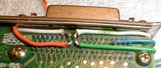
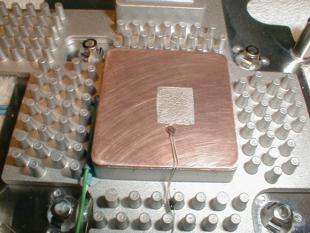
Damn, those pins are tiny!  I won't tell you how hard it was to solder to them, but you get the idea from how hot the wires got.  Compared to the nice fine traces on the motherboard, the individual wires from some cat 5 cable look big and clumsy.  A bit of hot melt glue holds the wires from going astray without making the bond too permanent.

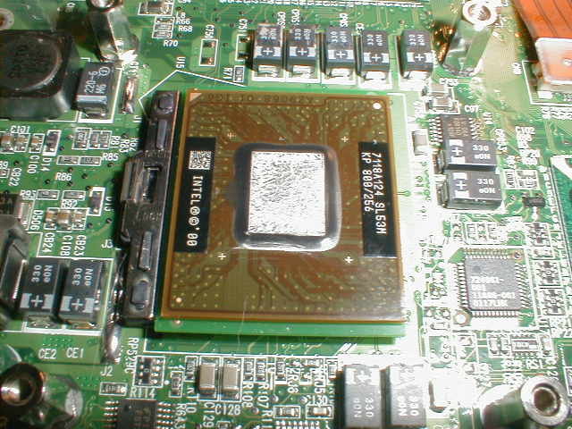
As you can see from the map of the connector legs, you need to access 5 pins on the connector; 4 sensor inputs and a +5 volt lead.  I soldered in the 5 wires (with some difficulty) and reassembled the system to check the results.  All I got was a constant reading.  After taking the laptop back apart and checking the connections, I realized that the motherboard might not have all of the necessary components installed on it to make the gameport work.  Since I had no schematic for the board, this was going to take some guesswork.  (Oh boy, I get to experiment with my new computer....)

Remembering that a game port works by a 558 timer (4 - 555 timers in one package) and that each of the inputs to the timer requires a capacitor to trigger the resistance reading, I set out to check whether or not the caps were installed on the motherboard.  This proved to be an exercise in futility.  The traces for pins 55 though 58 were buried in one of the layers of the board that I could not see.  There was no way to follow them to check for components on each path.

Time to trust in my intuition.  I surmised that the lack of caps was the probable reason that I was getting the bad readings.  I grabbed a spare sound card with a gameport output and searched for a value for the caps. This ended up being .01µF on the sound card I had.  That sounded like a good place to start.

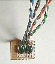
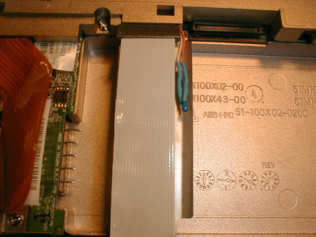
I made up a small circuit board using the schematic above, and attached it to the top of the motherboard.  The circuit requires a ground, which I picked up from the USB connector.  This had a nice large pad to solder to.  The circuit board has 6 wires out to the motherboard ( +5 v., ground, and the 4 sensor lines) and 8 wires for the sensors (4 pair - each pair consisting of a +5 v. line and a data line).  This is a lot of wire to be stuffed in such a small area, but it fit with some gentle persuasion.

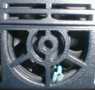
Next, the 4 pair of wires were fed outside the laptop case and the laptop was reassembled.  Thermistors were attached to the wires.  I crossed my fingers and booted up the computer.  Success!  I got good readings from all 4 sensors.  Wonders never cease.

After calibrating the thermistors, I got to take the laptop apart again.  It was time to mount the sensors.

Heat Sink and Sensors
Back into the case, the heat sink came out and the thermal tape was removed from the mating surface.  The surface was polished flat.  I cut a piece of sheet copper to fit the processor pedestal and used a burring tool on the drill press to make a small indentation for a thermistor.  The thermistor is an inside unit from a Radio Shack thermometer.

Next I used some 1000 grit wet and dry paper to sand the copper sheet flat.  The sheet was set on the pedestal with a thin layer of Arctic Silver thermal paste.  Having one extra layer of thermal paste is not a preferred method of getting better thermal transfer between the processor and heat sink, but hopefully the copper will transfer more heat to the sink and the end result will even out.  I'll have to run some tests to check this at a later date.

In the picture (above left); you can see one sensor (left) for the sink and one for the new copper heat spreader.  Both pictures; Checking the pattern of the thermal compound to make sure the heat sink gets good contact.

With two sensors remaining to be mounted, I chose to place one as close as I could to the outside of the case.  The best place I found was in between the fan grill and fan.  Unfortunately or fortunately (depending on your point of view), the fan comes on rarely and the fan intake serves as an exhaust port for the laptop's internal heat.

I am trying to get my hands on some information that will tell me how the fan is controlled.  I would prefer to be able to dictate at what  temperature the fan starts running.  During long sessions while plugged into AC, I have seen the processor and heat sink temps climb as high as 138°F (59°C) without the fan coming on.  This seems a bit warm to me....

I mounted the remaining sensor above the battery, which is a bit to the right and below the touchpad.  This sensor runs a few degrees cooler than the sensor mounted by the fan when the laptop is run on wall current. 

gp_TempL

The last item on the list for the initial stage of this project was to get some software running to show the temperatures.  The only program I had that would work with Windows 2000 was gp_Temp5.  Unfortunately for this project, gp_Temp5 was written to interface with Motherboard Monitor and MBM doesn't do much of anything unless you have temperature monitoring built into the motherboard.

I've just done a complete rewrite on gp_Temp5 to have it display the temps in Fahrenheit or Celsius on the title bar and to shrink the program down to banner size so I can run it "always on top."  I have added temperature logging and cleaned up the interface a bit.  It's available for download here - in case you're crazy enough to duplicate this project.

As I spend a lot more time running redhat than Win2k, I'm working on a temperature display to run on the Gnome desktop.  For now, I have a small script to display the temps in a terminal window.

In conclusion
This project turned into quite a bit more work than I had originally envisioned; however, I'm pretty pleased with the outcome.  While I would have preferred to have a nice Winbond chip do all of the temps and voltages for me, at least this solution works reasonably well and I can keep an eye on how warm things get. 

The laptop still looks stock - with the exception of the thermistor peeking out from the fan intake.

After a week or so of running the monitoring, I'm finding that this laptop runs pretty warm.  I need to put some energy into trying to get some more information on the fan circuit and see if I can control it.  Another project to add to the list.

All things considered, I was pretty lucky that my hunch was true regarding the lack of capacitors, but I'll take a bit of luck anytime.

Review and dual booting
Disassembly
Building the circuit