
|

Where I had started with a 2" x 1" x 5"
aluminum block before, this block got cut down to a little under 3 inches.
Where I had used 7 water passages of the same diameter, I went to 4 passages
in 2 different sizes. As you might imagine, this would reduce the
ability of the cooler to remove heat from the dual 30 mm TECs. However,
with the great performance I got from WC3, I figured that it was worth
a chance.
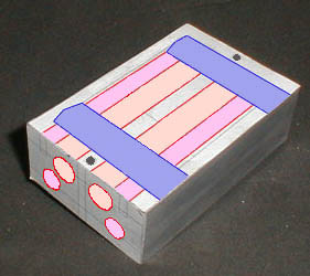 |
As I progress in making prototypes, I have found that I need to be able to "see" my ideas in as many different ways as possible in order to work out the bugs before I build it. I'm finding that just doing some CAD drawings isn't enough. One way that I've found that works for me is to tape my drawings to the raw piece of metal and stare at it for a while. After a few days of it sitting next to me, I have a better feel for if it will work or not. The picture above has been colored in to show the different passages but with just the lines laid out, it sat beside my computer for a couple of days while I revised and re-revised the dimensions. Some paper and double-sided tape saved me from having to machine it more than once.
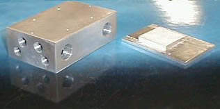
I drilled the four end passages on the
drill press, as I had with the last cooler. These would end up being
capped with set-screws. Two larger holes were drilled in the side
of the block for the water inlet and outlet. These would receive
brass nipples to attach the water lines. On this cooler, I added
two more holes perpendicular to the water passages. These would be
for what I hoped would be a way to mount the cooler securely to the 370
socket. Four more shallow holes were drilled and tapped to accept
the nylon screws that would hold the cold plate to the cooler.
 |
As you might be able to tell from the picture, this cold plate is a little thicker on the base (where it attaches to the peltiers) than the plate on WC3. You might also notice that the square where the slug will fit is off center. Amazingly enough, this is because the 370 socket holds the processor off center. It was while thinking about the fact that the processor was not centered between the "hold down" tabs on the socket that I began to realize that whatever method I came up with to hold the cooler in place had to take this into consideration. It would be important that the tension holding the cooler to the socket be able to be regulated. Otherwise the fact that one side of the cooler was farther from the fulcrum than the other would tend to tilt the cooler toward the longer side if equal pressure was applied.
Designers of the socket 7 / 370 heat sinks
we usually see get around this by making the retainer spring free floating
and have it contact heat sink only where the spring's pressure will align
with the slug of the processor. Since I couldn't manufacture a free
floating spring, I would need to be able to adjust the tension on each
end. Fortunately, as you'll soon see, this wasn't hard to accomplish.
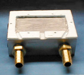 |
At this point it was now time to start
insulating the TECs. Again I chose to use the DOW R3 house insulation
which I "machined" down to the proper thickness and cut with a razor knife.
The picture above shows some of my "home made" heat sink compound spread
on the cooler. I'll go into the particulars of the compound in another
article, but it is a cheap alternative to the zinc oxide based compounds
being sold commercially.
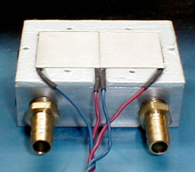 |
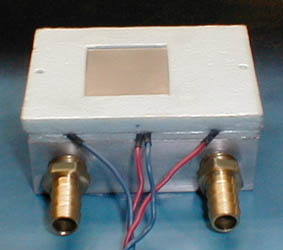
The peltiers are installed. Before
installing the next layer of insulation, the cut-outs for the peltier wiring
get a little silicone sealer to prevent air from entering and moisture
from exiting the TEC cavity. (In the couple of months that I have
now had this setup running, I have yet to see so much as a drop of moisture.
This impresses me considering the different component temperatures routinely
range from -17°F to past +70°F.)
 |
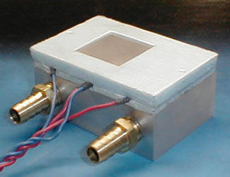
The amount of offset of the cold plate
is easy to see here. This cooler has turned into a pretty clean looking
package. You'll notice that, like WC3, the cold plate is slightly
recessed in the insulation. This allows for good contact between
the raised slug of the Celeron and cold plate while sealing the slug from
the outside air. The less air that can contact any of the cold parts,
the less chance of condensation happening.
 |
With the basic cooler package assembled, it's time to talk about mounting the cooler to the socket.
|
|
|
|