
|

With the first piece of insulation cut,
I set it in place and added the two 30 mm TEC's with a thin layer of thermal paste. These
peltiers are potted, which means that the edges of the TEC are sealed with a substance
that looks similar to silicone sealer. This does two things.
One, it keeps condensation from forming inside the TEC and causing trouble
with shorts and two, it allows for the TECs to be placed side by side (touching)
without concern for short circuits.
 |
The TECs were wired in parallel so each
peltier would get a full 12 volts. I have been powering my peltiers with an external
power supply for a while now. I use a 235 watt AT style power supply from an old 486 box. I started
doing this to be able to get the peltiers really cold before booting the system.
It's not really necessary for most situations, but you never know when I'll want to try booting
to some ridiculous speed where a cold processor on boot-up makes all the difference.....
 |
Next to get added was the cold plate.
I'm a bit up in the air about the design for this plate. As I said, the
plate's thickness started at 1/4". I removed material from around
the center block where the processor's slug will attach, until the thickness
of the plate was about 3/32". This left the raised area at 5/32".
My concern is that the 3/32" portion is not thick enough to draw away as
much heat as the Celeron will produce. I plan to experiment with
some different thickness' and see what happens.
 |
Another layer of insulation is added.
This one has been relieved to have the cold plate fit snugly inside it.
The insulation sticks up a bit higher than the square of the cold plate
so that when the Celeron is attached, it seals the slug tightly around
the circuit card of the PPGA assembly. You will remember from previous
articles that the PPGA assembly has been coated in polyurethane to prevent
short circuits in the event of condensation. (Hmmm, "In the event of condensation"
is being overly optimistic. Condensation will occur!)
 |
To quote a line from history, "Houston, we have a problem." The problem was how to attach this darn thing to the 370 socket. I had originally envisioned running spring clips around the 2" side of the cooler and threading them under the 2 tangs on the side of the 370 socket. Wrong. No matter how many different designs I came up with, I could not get the cooler to fit tight enough to the Celeron. I tried wire ties, helical springs, big "C" shaped springs, everything I could think of (and I can think of some pretty weird stuff.) Nothing held the assembly together with the permanence that I was looking for.
Slowly, the plans for water cooler #4 started
to take shape. But what to do with this one? I wasn't about
to give up on it without finding out how well it cooled. I did have
these big spring clamps I use for holding projects in place during gluing.....
Ugly? Yes. Totally impractical? Yes. Perfect, I'll use
one! And so it went together for testing.
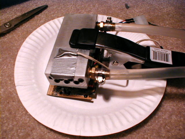 |
If you can get past the fact that this setup looks pretty Mickey Mouse, the numbers are pretty impressive. Without the additional insulation I normally use to guard against condensation, this one pulled moisture out of the air like a magnet. However, the performance and the ease of building it let me know I was headed in the right direction.
One thing made itself apparent pretty quickly.
This design had no problem dissipating the heat of the dual 30 mm TECs.
There was more than enough water flow through the cooler to pull the heat
out to the radiator. (For those of you who aren't familiar with the
radiator side of this water cooler, the pictures and description can be
found here.)
 |
 |
Because I had this cooler held together with a big spring clamp and it had no extra insulation to keep moisture from condensing on the 370 socket and adapter card, I quickly got to work on water cooler #4. A couple of design decisions were made.
1. The cooler performed better than expected and could probably be made smaller. This would help in mounting it to the 370 socket.
2. I could probably get away with fewer water passages. This would save some time in building it.
3. I would increase the thickness of the cold plate where it covered the peltiers to help with the removal of heat from the slug.
Water cooler #4 is on its way.