
|

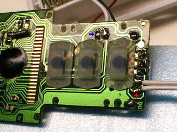 |
Solder the unattached outdoor probe to
the two solder pads that you removed the indoor thermistor from (red arrow).
For identification purposes, the blue arrow shows where the original outdoor
probe wires are attached. At this point, this wire has nothing on
its other end.
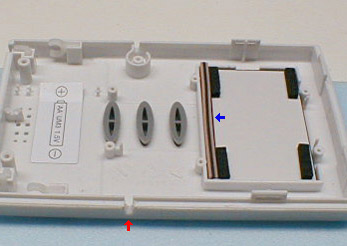 |
Since there was only one wire leaving the
case in its stock form, we will need to provide a slot (red arrow) for
the new lead to exit the case. I used a small, round (rat tail) file
to form the slot. The blue arrow points to the area of the liquid
crystal display that contacts the fingers on the circuit board. When
you are reassembling the case, it is important that good contact is made.
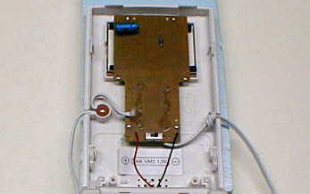 |
Install the seven small screws, making
sure that the two center screws below the display are snug (but not too
tight) before tightening the rest of the circuit board screws. Using
an "X" pattern to tighten the screws will help insure that the circuit
board is tightened evenly. Slide the knot for the new wire you soldered
in so that there is not too much loose wire inside the case and tighten
the knot a bit. There is no need to make this knot too tight.
It is just there to prevent the wire from tugging on your soldered connections.
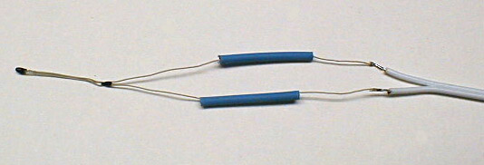 |
This is the toughest part of the modification.
After stripping the ends of the probe wire and threading a couple pieces
of heat shrink tubing on the thermistor leads, you get to solder the thermistor
to the probe wire. The reason that this is tough is that it either
requires 3 hands or a way to keep the leads in contact with each other
as you solder them. Twisting the ends of the wires together before trying to solder
them helps, but 3 hands works better. Now slide the heat shrink over the
soldered joints and shrink it with some heat from a lighter or the metal barrel of the
soldering iron.
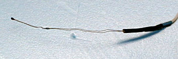 |
It's hard to see in this picture, but I
added a couple more pieces of heat shrink to hold the wires together.
This is optional. Notice that the thermistor is pretty small and
the wires are very thin. The wires happen to fit nicely between the
socket 370 / socket 7 - socket and the processor, so you can monitor the
processor's temperature from the back of the chip.
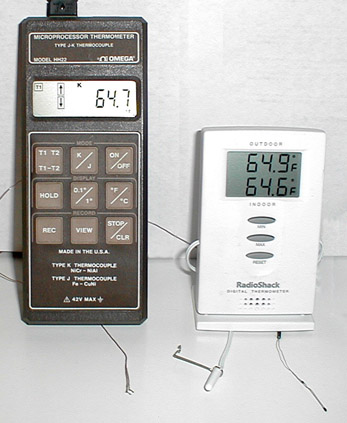 |
I've heard comments that some think that the thermometers are not very accurate. This may be true if you compare this inexpensive unit to thermometers costing much more. However, a couple of degrees off throughout the range is more than accurate enough to tell what the processor or heat sink are doing at a particular time. The displayed temperature of the two probes measuring the same temperature does vary. However, as you can see, at a rather chilly room temperature, the difference between my $15 thermometer and a calibrated Omega thermocouple thermometer (thanks again Charlie!) using a type "K" thermocouple is negligible. At 120°F the RS thermometer is off by a few more degrees.
So there you have it. No more excuses that your socket 7 has no temperature monitoring. If you want to know the temperature of the processor's case, you have the means.