
|

Shumatech
DRO-350 Repairs
July 4,
2009
When I
purchased my DRO back in 2006, I also purchased a spare. I was
planning on putting it on a lathe, when one arrived. I built and
tested the second PC board, but never got around to installing it
on the lathe. Fast forward to May 2009 when I purchased two more
Jenix scales for the mill. After three years of running the
Chinese scales on the Y and Z axes, I decided to go all glass
quadrature scales. The mill's current Y scale, which was a 6" HF
caliper had developed a bit of play in the gibs and needed to be tapped
a couple times to center it or it would read a couple thousandths of an
inch plus or minus the actual coordinate. I could have probably
pulled the scale apart and cleaned and lubed it, but I have grown fond
of the Jenix I'm running on the X axis and the fact that it is always
repeatable within its specifications. I consider the Jenix a step or
two up from the Chinese capacitance scales.
The DRO had developed one
problem in its display. The center segment (labeled "G" on the
display diagrams) of one
of the Z readouts had stopped illuminating. I planned to take
care of this while I set up the box to handle another two Jenix scales.
Once I got inside the DRO
and started tracking down the issue with the center segment, I found
that the "G" segment of DS8A had burned out. This proved to be a
bit more of a problem than I expected as the MAN6940 Seven Segment LED
Display is no longer a stocked item at my usual electronics
suppliers. I ended up ordering 10 replacements (630-HDSP-523E
from Mouser), in case I wasn't pleased with just replacing the one with
the problem. I figured I'd just pull out the other DRO-350 board
and swap it with the spare. This would give me plenty of time to
replace as many of the displays as I needed to get a nice looking read
out.
What I didn't count on is
that I would be careless and blow up the second board. Yep,
that's right, I plugged in the power plug to JP6 reversed. As
soon as I realized what I'd done, I knew that there would be
problems. There were. I now had missing segments on the X
display and nothing on the Y. Nothing. No r4 message
at boot up, no no read out from the scale. No nothing.
Well, that's not entirely true. If I jumped across the number 12
and 13 pins of U10, I got the decimal points to light up.
However, that doesn't tell me enough to fix it. Only the Z axis
showed what it was supposed to, "nnill."
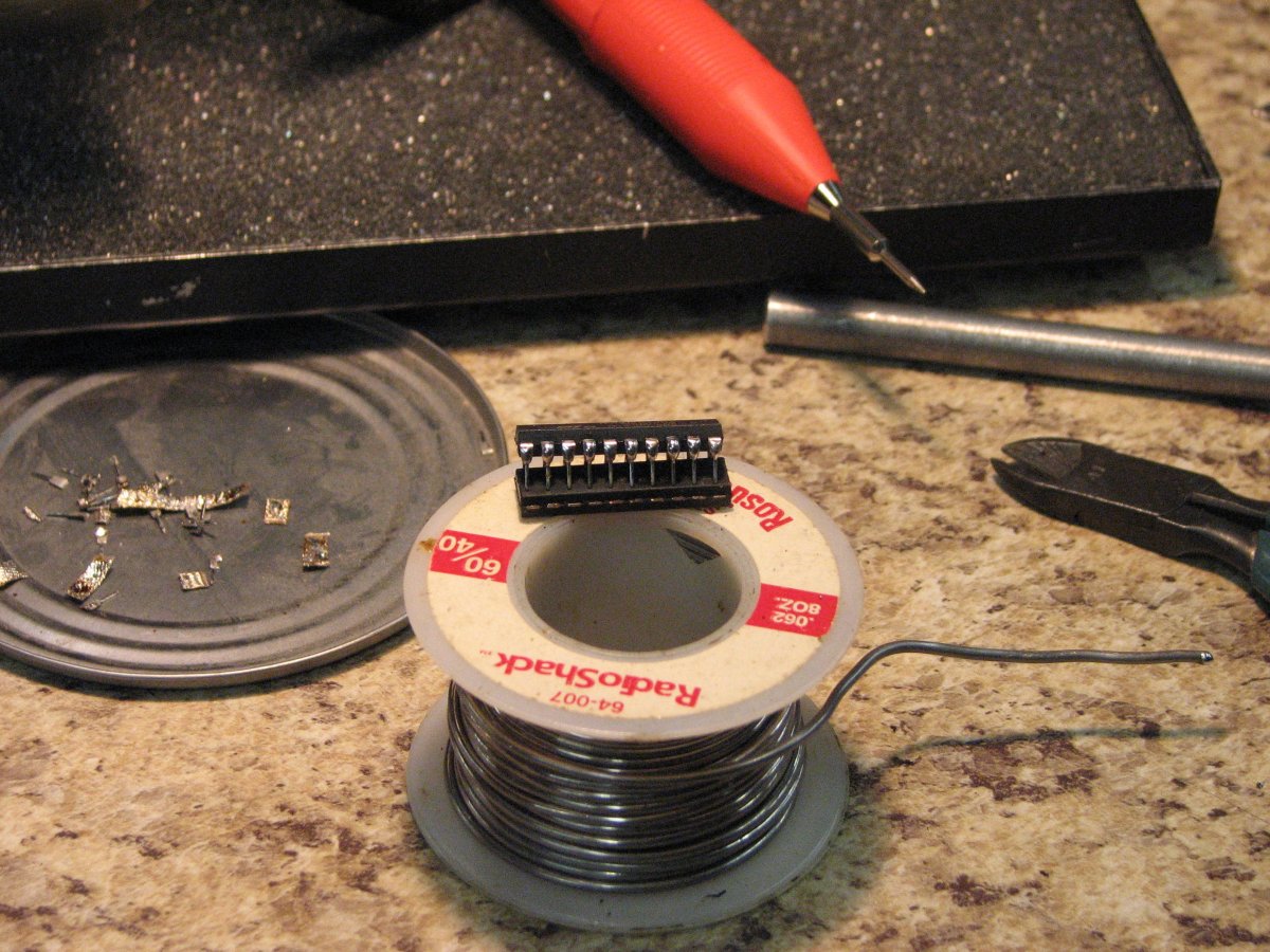
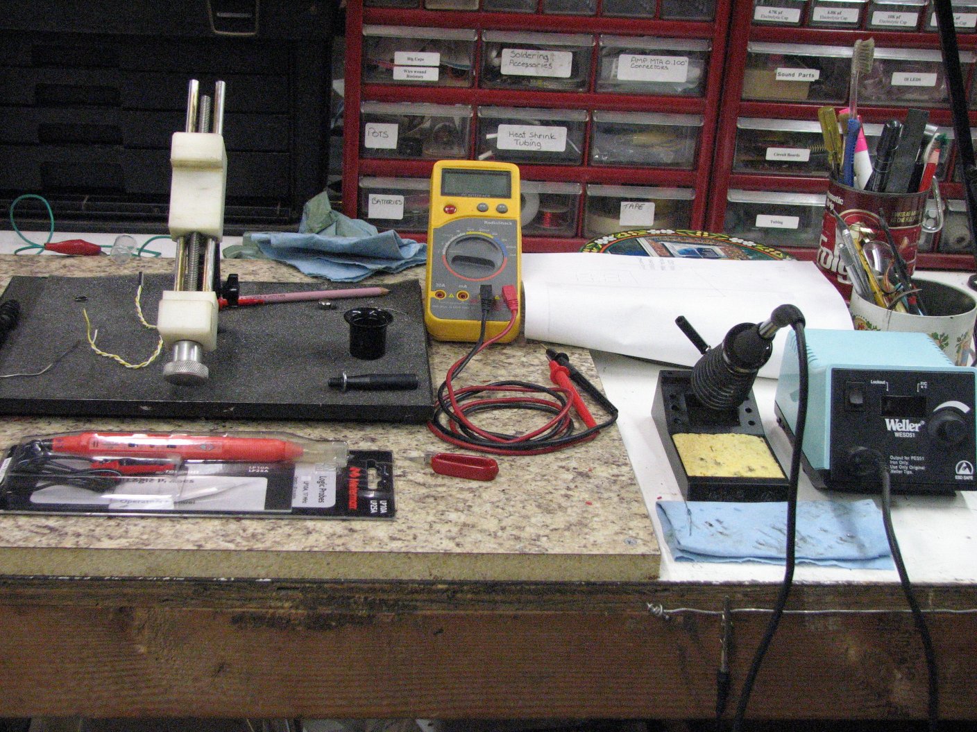 |
| Tools
used for the repairs. Digital volt/ohm meter, logic probe, circuit
board vise and soldering station. My anti-static strap hangs from the clip, on the right. |
I was in a heap of
trouble. I don't have a oscilloscope. All I have is a
decent DVOM and a
logic probe. The
one thing I had
going for me is that I had a working board to compare the blown one
to. That and all of the great posts by Lester and the rest of the
guys who really know the DRO-350 on the Shumatech Yahoo group. I
had also purchased extra of all the parts necessary to build the
DRO-350.
As I read through the
posts, I found that I wasn't the only person to try and repair a
DRO-350 without a scope. It seems that without a scope, it
makes the process of deducing whether a part is good or bad a bit
harder. Harder, yes. Impossible, no - and since I am sure
that I am not the only person to fry a board, I thought that sharing my
method of repairing mine might help someone else in a similar situation.
The first thing to know
about the display circuit is that each of the 3 LED displays
per axis is actually two displays. Each of the 6 displays (2 X 3) is
comprised of 8 anode segments (7 bars that make up the parts of the
number plus the dot) and a cathode.
Each segment is given a letter designation. Letter "a" is the top
horizontal bar, "g" is the center bar and "dp" is the dot. Pins 13 and
14 of each double digit display are the two cathodes. Aside from
the two cathodes which selectively complete the circuit though the
ULN2803A chips , each of the other 8 segments in each half of the
display are connected to every other same letter on the other 5 half
displays. This means that all Y axis "a" segments are on the same
circuit and you should be able to use your continuity tester to show a
completed circuit between all of the "a" segments. This would
include three number 11 pins and three number 16 pins of DS7A/B DS8 A/B
and DS9 A/B. If one pin lacks continuity, look for a broken trace
on the board or a bad solder joint.
Each segment is lit by a
circuit completed from the plus side (+9 volts) of the wall wart
flowing
ultimately through one of the 150 Ohm resistors in R12, R13 or R14,
then to the lettered segment, then out the cathode on pin 13 or
14 and returning to the minus (-) side of the wall wart. Between
the
resistors and the PIC, there are the display driving ICs that dictate
when the segment
will be lit. On the anode side, we start at the PIC microcontroller on
pins 11 through 18, then to the 2 through 9 pins of the
M74HC573B1R IC and out the opposite side on the 12 through 19 pins,
then
to input pins (1-8)UDN2983A and out through (9-16), then to the
resistor pack. If you look at the circuit
diagram, you'll see that the signal enters on one side and goes out
the opposite side - straight across the IC. Once you get to the
display units, you need to read the pin numbers on the schematic as the
representations of the displays are not sequentially numbered like the
ICs.
On the cathode side of
each display, the ending points are pins 13 and 14 of each half display
chip. Starting from the PIC on pins 5, 6, and 7, the signal goes
to the 1, 2, and 3 pins of the M74HC238B1R IC, then out on the 9 through 15
pins and on to the 1 through 7 pins of the ULN2803A and out the13
through 18 pins to complete the cathode circuit on pins 13 and 14 of
each display.
Confused? Trace it on the display and microprocessor circuit
diagrams
which
will make it easier to follow.
To add one more layer of
complexity to diagnosing the display, it is multiplexed. The data
0 through 7 lines carry the display data and the column 0 through 7
lines complete the circuit one column (each half display) at a
time. If I view the display through the viewfinder screen of my
digital camera, I can see each column of the X, Y, and Z displays light
brightly, one column in all three rows at a time, across the 6 columns
of the display and seventh column, the indicator LEDs. With each column
lighting for a fraction of a second, it tricks the eyes into seeing a
solidly lit display. Photos of the display sort of show this, but
at the shutter speed I was using, it shows as two columns bright and
the remainder a bit dimmer.
 |
 |
| In
this picture, we see the "ones" and minus sign columns lit. |
In
this image, we see the hundredths and thousandths (and 0.0005" dot) lit. |
| Each column is lit in sequence. My camera's shutter speed is such that it is capturing about two columns in a bright, or power on, state and the rest of the columns are dimming. They will be refreshed on the next cycle. The effect is more noticeable on the larger images. | |
I started with the PC
board out of the box and held up so that the buttons would not get
pressed accidentally. The only thing plugged into the board is power at
JP6. Once plugged in, the boot message appears. In my case, only the
top and bottom lines were lit and the characters in the X display were
missing some segments. I left the boot up message on the screen and
began my tests.
I looked at the schematic
and found the VCC and grounds for each of the ICs and tested these with
a volt meter. With those are reading as they should, I grabbed my
logic probe and started at the number 11 pin of the PIC (Data0). I
checked it for a pulse. Good. Then on to pin 2 of U7, the M74HC573B1R
on the X axis of my mill display. This display was mostly working, but
missing the top center (a) segment all the way across the display. I
got a pulse at the 2 pin, but only a low logic signal with no pulse on
the output pin 19. This was telling me that I had at least one
bad circuit inside this IC and it needed to be replaced. I then
checked the input and output of U10. This is the same M74HC573B1R IC, but on the Y axis. Pin 2
showed a pulse, but pin 19 showed nothing. I checked it with the DVOM
and it was reading a couple microvolts. The Y display was
entirely
blank, so I wasn't surprised. On to the working Z display's M74HC573B1R IC. Pulsed input, pulsed output.
One of the three ICs checked out correctly, but this was only the first
pin check. With the information I now had, I knew that I had two
bad ICs, but I went ahead and checked each circuit from the PIC to the
output side of the 3 M74HC573B1R ICs. The remainder of the
pins on the X axis M74HC573B1R IC showed good. The IC on
the Y axis had 0 pin pairs that showed a pulse on both sides of the IC
and the IC on the Z axis showed all pins good with a pulse showing on
both the input and output side of the IC.
It really didn't make much
sense to trying and follow the circuits to their next step until I
fixed what I knew (or thought I knew) was wrong. To remove the
two ICs, I used a hobby knife with a newly sharpened #11 blade. I
placed the side of the blade flat against the IC with the sharp edge
between the first two pins of the IC. By rocking the knife
toward, then away from the pins, I used pin 2 as a fulcrum to cut pin
1. Then pin 3 as the fulcrum to cut pin 2. If I had a pair
of diagonal cutters small enough to fit between the pins, I could have
used those, but my smallest pair of cutters were too big for the
job. Once I had cut all but the two end pins from the IC, I
clipped the last pins with my diagonal cutters and removed the plastic
portion of the IC.
 |
 |
| The
leads for U10 have been clipped and the IC is ready to be removed. |
The new IC sits on top of the old IC. The new IC has its pins pretinned. |
I then used my soldering
iron and a pair of tweezers to remove the pins from the circuit
board. The next step was to use some rosin coated desoldering
braid to soak up most of the solder and clear the holes. The last
step was to wash the area off with isopropyl alcohol and dry it with my
heat gun. Soldering the new chips in was a bit tougher than it
was when the displays weren't on the board. I made this a bit
easier by tinning each of the legs of the IC before inserting it into
the board. I also left a little "blob" of solder at the top of
each leg so that a quick touch with the iron would melt it and flow
down the pin. I think this helped to get enough solder on to each
pin quickly and avoid overheating the IC. With some talk about
the possibility of the through-holes not being connected from top to
bottom, I wanted enough solder to solidly connect each pint to both the
top and bottom of the circuit board. Also, be wary of your
soldering iron tip. It is very easy to
touch the iron to the displays and produce melt marks. I
put a piece of aluminum duct tape over the sides of the displays to
help me avoid making a mess of the plastic. I ended up with only one
small burn that won't show when the case is back in place, so I
consider myself lucky.
I plugged power back into
the board. This time I had all displays working for the boot up
message. I was quite pleased with myself until I plugged in the
scales. The second from the right half display on the Y axis
(DS6A)
wasn't showing anything. Nuts! Looking at the schematic, it
appeared that the only thing that could cause this would be the U12
ULN2803A IC wasn't getting a ground to pin 14. I confirmed this
by checking the input #2 pin (pulsed) and output on pin #17 showing
nothing with the logic probe and microvolts with the DVOM.
I replaced the ULN2803A IC and rechecked the
display. Everything worked with my Chinese capacitance
scales. However, I could only check 2 of the axes at once as I
had been running a Jenix on the X and it was still on the mill on the
other side of the room. I did have a 12" Chinese caliper that I
could wire up, but I still wanted it to be able to be used as a
free-standing caliper. I decided to add a 0.1 µF and a 100
µF cap in the battery compartment, then add a MTA-100 4 pin
header to the scale's header. I'd then be able to plug either a
scale cable or battery in that spot. This would allow me to use
the caliper for testing a DRO or as a stand-alone caliper. Not a
big modification, but it works like a champ.
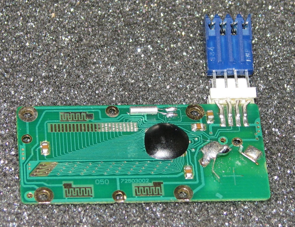 |
 |
 |
| Caliper
circuit board with MTA 4 pin connector attached. |
Battery
plugged in with a female MTA connector. |
Unplug the battery and plug in the scale cable |
I added the two additional
QCC-100 dongles and checked
again. Now I had the X and Y display working and no Z. Not
even a zero on the Z display. I swapped the QCC-100s and the
problem moved with the QCC. With the logic probe, I checked the
output pins at 6 and 7 on the little PIC. No pulse. I had
one extra PIC for
the QCC-100 and checked that on my PIC programmer. It checked good, so
I desoldered the old PIC and soldered in the new. 8 pins is about
the extent of my luck in getting an IC out in one piece without ruining
the pins or getting the IC too hot and killing it. Same
issue, no pulse and no readout on Z. After checking the traces
for the tenth time, I figured it had to be the oscillator, but no, the
two spares I had made no difference. I was getting a bit
frustrated, so I ordered a new QCC-100 kit. When it came after a
few days, I had been thinking about the problem and reading the posts
on the Shumatech Yahoo group. I believe it was Lester who had
stated that he had gotten a bad batch of oscillators. I was now
pretty sure that this was my problem too. I tried
the newly purchased oscillator in my broken QCC-100.
Success. It turned out
that over half of the oscillators I had purchased a few years ago must
have been
bad. What are the chances of getting 3 bad ones in a row?
Probably about as good as winning the lottery. I've looked
carefully at the parts and they look fine. I guess it might be
possible that they were mis-marked, but whatever the reason, it is not
the type of thing that one would expect.
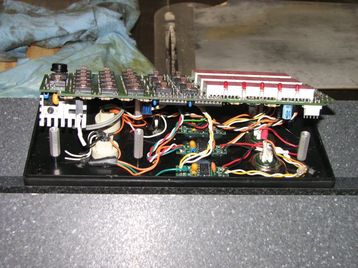
I now had my spare DRO
working, but I still needed to fix the one bad display on the DRO on my
mill. I decided that I needed the DRO working now, so I ended up
swapping the repaired board into the old
case. I had purchased the extra Jenix connectors so that I could
plug
the Jenix cables straight into the DRO and spent some time adding the
QCC-100 circuit boards inside the DRO case. Once I had this done,
I needed to decide whether I would try to run the 3 Jenix scales from
the 5 volt voltage regulator on the DRO-350 or add a regulated 5 volt
wall wart to power the scales. I re-read Scott's post on the
situation and decided
that since I was using a 9 volt regulated wall wart for power, I would
probably be safe with running everything off the one power
supply. Just to be on the safe side, I milled up a large heat
sink that would attach between the two regulators on the circuit
board. On the side of the U17, the regulator that supplies the
1.5 volts, I made a thin plastic insulator and used a nylon 4-40 bolt
to attach the heat sink. On the side of the 5 volt regulator, I
added some good heat sink paste and a metal 4-40 bolt. This is a
really big chunk of aluminum and it soaks up a lot of heat. As
you have probably figured out from my description, the idea was to not
have the bases of these two regulators be joined electrically.
Had they both been single voltage regulators with grounded bases, it
would have not mattered, but U17 is an adjustable regulator and
grounding the base in this circuit would have been bad. As it
turned out, the big heat sink seems to work well and after a full day
in the shop with the DRO on, the side of the case isn't even
warm.
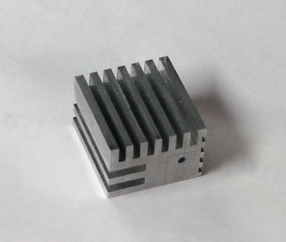 |
 |
| A
healthy block of aluminum makes a good heat sink. |
Heat
sink, QCC-100s, and the Jenix connectors just fit. |
I spent a couple days
working
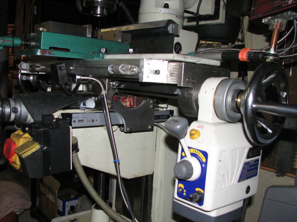
on the mounts for the Jenix scales.
I planned to keep the locations of the new scales in the same places as
the old ones, but both mounts were going to require new holders
fabricated as I chose an 8 inch scale for the Y. An 8 inch Jenix
is actually 14 inches long. This is about twice the length of the
capacitive scale it was replacing. The extra length would come
very close to the end of the knee, so I needed to shim the scale a
little further out so it
wouldn't interfere with the body of the mill. It turned out that
I only needed about an extra fraction of an inch, so the scale's mount
is
still very robust. I used a 0.25" thick by 1.00" wide length of
6061 aluminum flat stock as a mount for the scale. The holes at
each end of the scales are slotted so that I could tweak the scale to
be parallel with the knee ways.
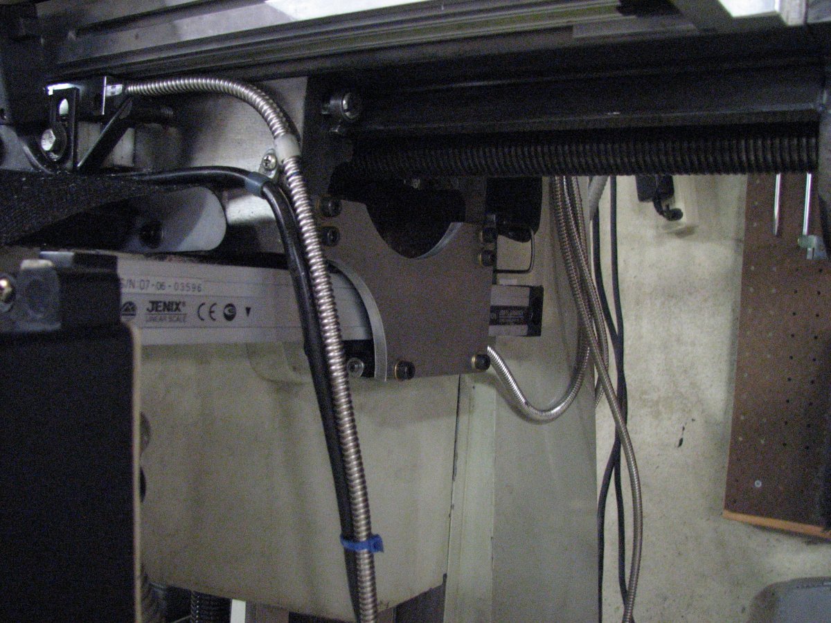
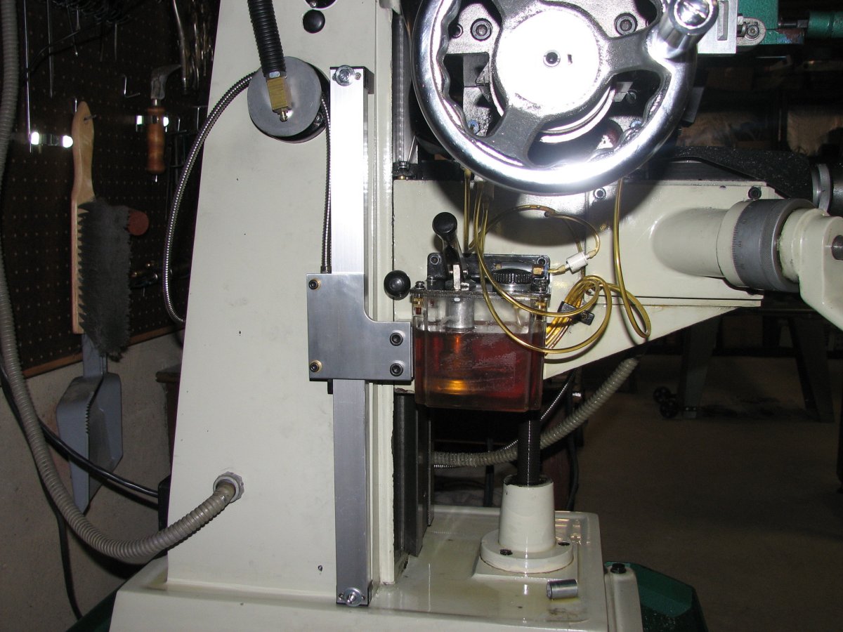
The Z scale was a bit
harder to mount. The side of the mill column is angled at about
3°,
so I had to take this into consideration when building the mount.
I initially made up a piece of 18 gauge sheet metal as the connector
between the scale head and knee. I used gage blocks between
the sheet metal and scale to check that the scale was as parallel to
the Z ways as possible. I used shim stock to achieve parallelism
and then pulled the mounts and used a sine table and gage blocks to
measure the length and angle of each mount. Once I was happy with
the measurements, I milled the mounts. I bolted everything back
together using the sheet metal as the connector and rechecked the scale
head to make sure that it ran parallel to the scale. Once I was
satisfied, I used the same 0.25" thick aluminum
plate I had used elsewhere to make the connector between the head and
the knee. There is no flex or deviation from parallel that I can
measure.
 |
 |
 |
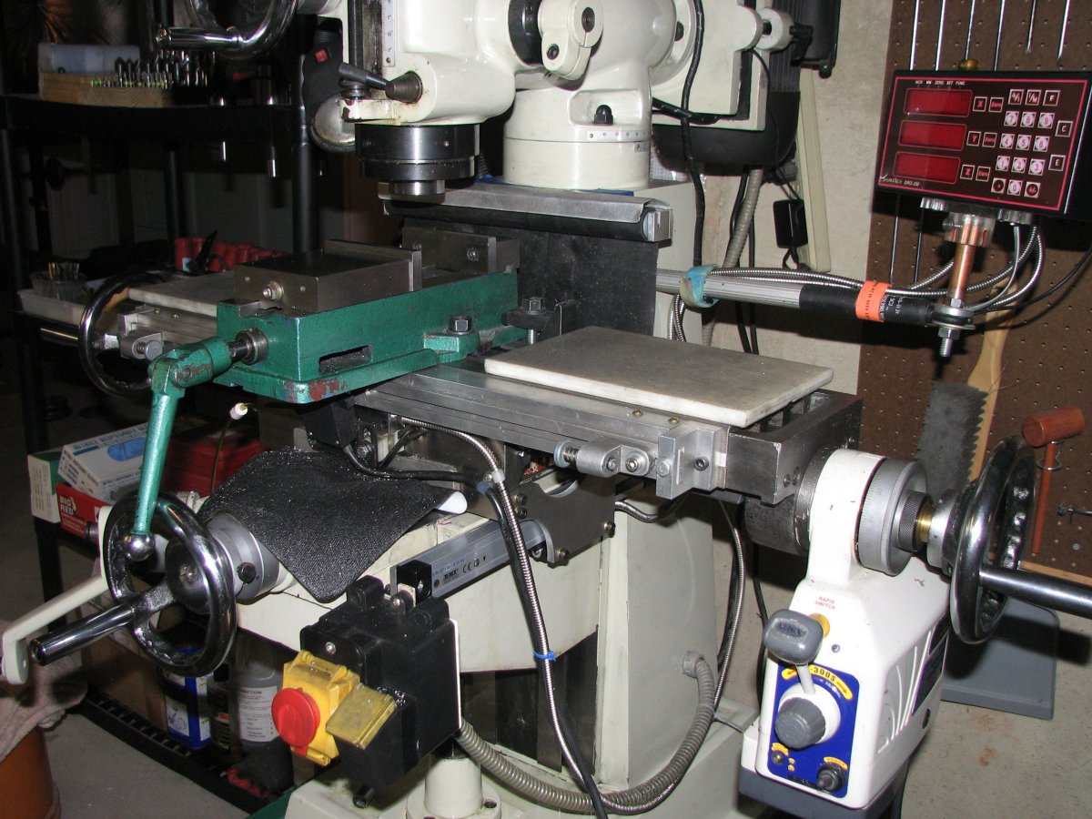 |
| Jenix
scale on the Y axis is a tight fit. |
At
about 14" long it spans the whole knee. |
The Z
axis mount keeps the swarf away. |
The
armored cables are cut to length. |
One last consideration for
the Z axis scale mount was that the open side of the scale needed to
face away from the flying swarf. While I do have a rubber guard
that keeps the chips away from the Z ways and extends far enough out on
either side of the ways to prevent a lot of metal from flying in the
direction of the scale, it won't catch all of the chips. Due to
the way the head was mounted to the scale and that I needed the cable
to exit toward the top of the mill, I would need to mount the scale
with the front side facing the mill's body. I considered taking
the scale apart and seeing if I could reverse the direction of the
head, but decided that I didn't want to take a new scale apart. I
built the mounts to conform to the plastic end caps on the scale and it
seems to work just fine. To keep the armored cable from flopping
around, I cut a disk from sheet metal and mounted it on the lamp
mount. I also added an angle adapter to the lamp base to fix the
bothersome way the lamp was originally mounted. Both the angle
adapter and the disk worked out quite well. The weight of the
armored cable keeps it tidy and the lamp no longer gets in the way of
my cuts. Once I had all the scales in place, I shortened the
cables and resoldered the plugs back in place. The most difficult
part of this little task was getting the shrink tubing the right size
to fit inside the plugs and not shrink while I was soldering the
connections. This was one of those tasks where it would have been
helpful to have a couple more hands.
So after about a week and a half of working and waiting for the QCC-100
parts, the scales were installed and the DRO had all its digits
again. The 2 new scales seem to work just as well as the one I
have had on the X axis and having the 5/10,000 indicator actually flash
between each thousandth is nice. I have the DRO filtering set to
0 and there's not a hint of jitter. Quite a nice upgrade.
I am not an electrical engineer. I believe my description of the way the circuit works is accurate, although a bit incomplete. If you find errors in my descriptions or diagnostic steps, I'd appreciate hearing about it.