
|

Sheldon 12"
Shaper - pg. 5
September 28 to October 14, 2015
After finishing
scraping the tool head and swivel block and reworking the lock, I
decided that I had to paint the tool head. I really hadn't planned
on stripping and painting anything on this machine at present,
aside from shooting primer on the missing front panel and the
repair I made on a side cover. However, after all of the work I
had done on the tool head, looking at the two different colors of
flaking gray paint and all of the chips on the tool head made me
decide to spruce it up a bit. Since I have started down this
slippery slope, I will also paint the other parts I have repaired
and put primer on. At this point, I don't plan to paint the whole
machine. I would rather get some time in using it. I've had it
since the end of May and only have about two hours total time of
using it.
I used some aviation stripper, then wire brushed, then sanded the
tool head, taped it off, and shot a couple coats of primer on it.
I really can't tell if the darker paint below the light gray with
a bluish tint was another coat of paint or maybe a darker primer.
I like the darker bluish gray better than the lighter color, but
many of the Sheldon's I've seen pictures of match the lighter
color. While I had considered having the original paint matched
and going with some Benjamin Moore Urethane Alkyd Industrial
Enamel as I had done with my South Bend lathe, I decided against
it and purchased some Steel Gray paint from Tractor Supply. I also
purchased some black and some blue. I would attempt to come close
to the darker color by mixing the paint myself. I've used this
paint before on one of my tractors and it holds up pretty well. It
doesn't seem to chip as easily as some of the other enamels I have
used.
After I sanded the tool head with 220 grit paper and put the
second coat of high fill primer on the tool head, I had some time
to kill before calling it a night. My next scraping job would be
to scrape the boss that the table support rides on. I also needed
to scrape the bottom of the support itself. I hadn't decided which
surface to start with at this point. To get started with this job,
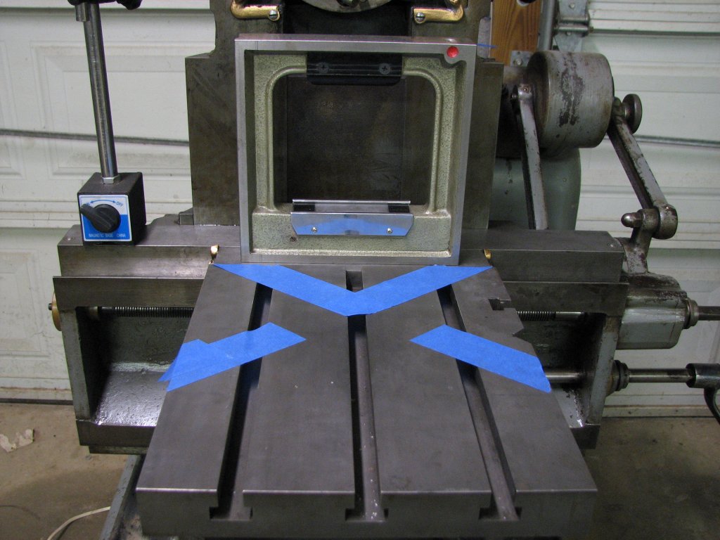
I first needed to map the surfaces I would be scraping. I set up a
magnetic indicator base on the bottom of the table and ran the arm
down toward the boss. I attached the DTI and measured the boss for
being parallel with the travel of the table and cross rail ways. I
measured in three positions: The rear side of the boss, the front
side and the center. All three measurements were within a couple
tenths of agreeing with each other across the length of the boss,
but the boss seemed to be out of square in two directions. The
boss was high on the left side by 0.0025". This was over 12 inches
of the 16.5" boss. Not terrible, but not to the Sheldon spec of
0.001" in 12" and I wanted to get it closer to 0.0001" if I could.
 |
 |
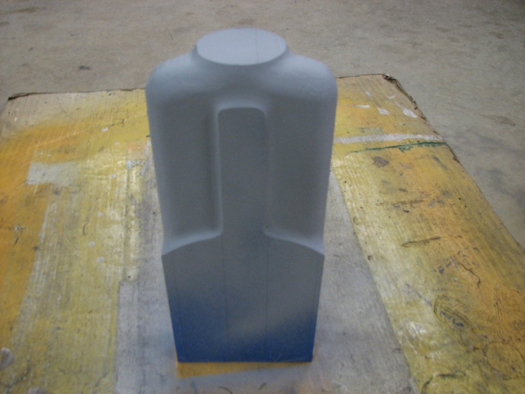
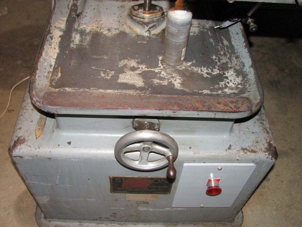
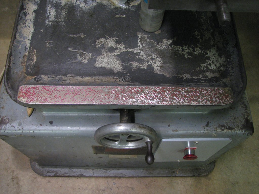
| With
the old paint stripped off of the tool head, I gave it a
couple coats of high fill primer. Once it dried for 24
hours, I again sanded with 220 paper. |
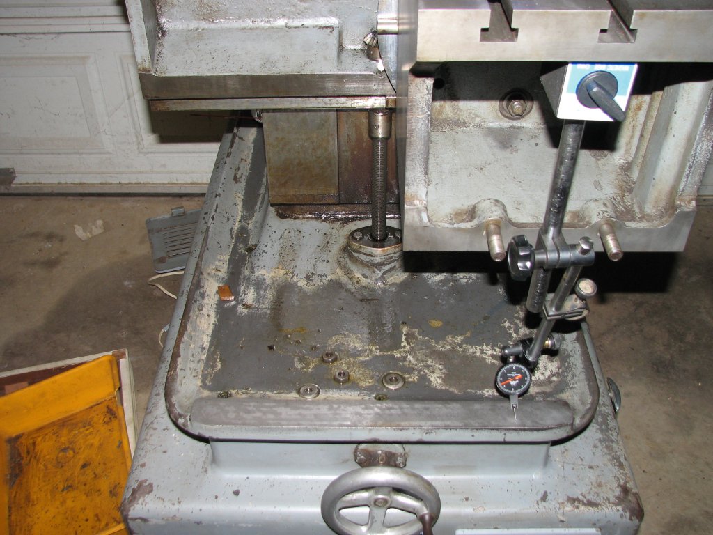
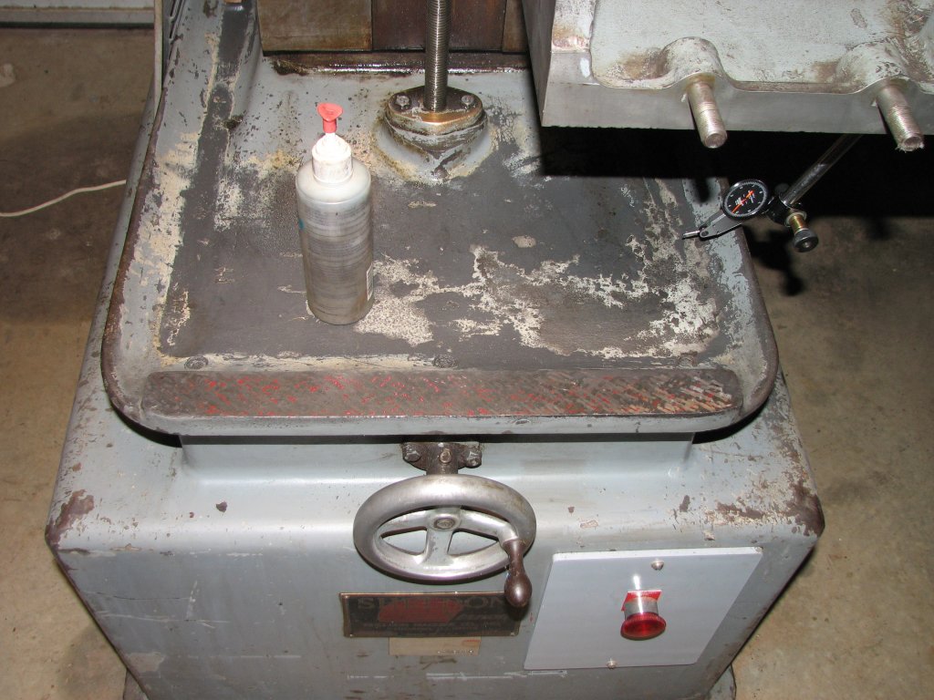
I
measured the top of the table support boss from left to
right. The boss was low on the right by about 0.0025" over
12". The boss is 16.5" wide. |
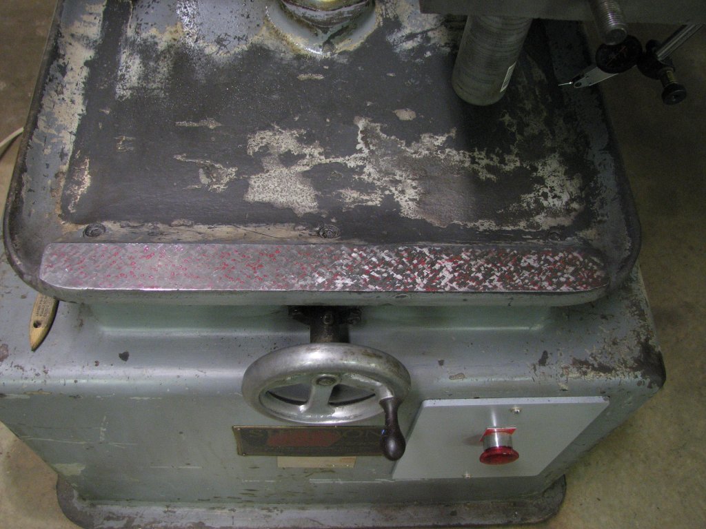
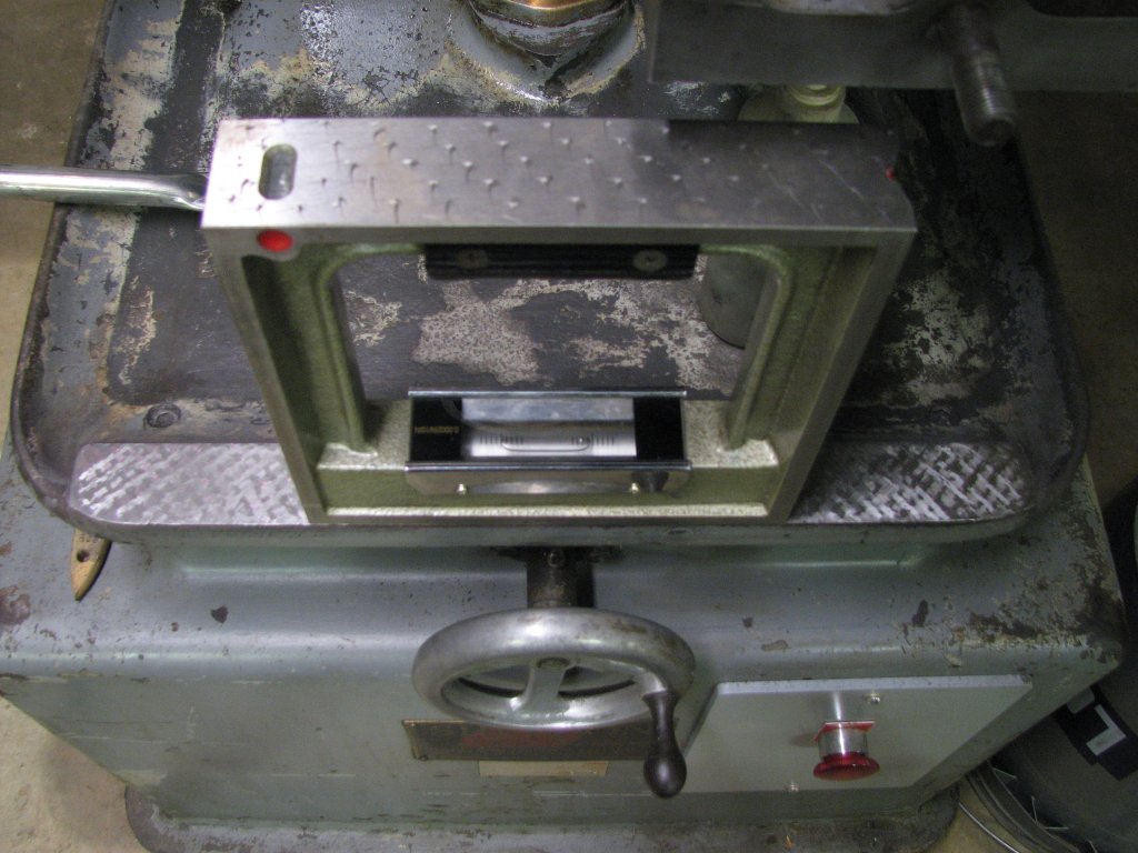
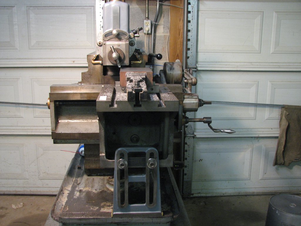
The next step was to measure the front to rear surface of the 1 9/16" wide (Y axis) boss in relation to the top surface of the table. I had previously measured the table in relation to the stroke of the ram and after adjusting the ram gib, had proven that the ram and table were in the same plane within 0.0001" over the length of the 12" table. Now I wanted to get the boss to match the ram and table as close as I could. I set my camelback straight edge on the table and attached the mag base for the DTI on the under side or the straight edge. I could now slide the straight edge across the table and read the relative height of the boss. This boss was angled a bit more than I figured it would be. About 0.002" in 1 9/16". That's a lot.
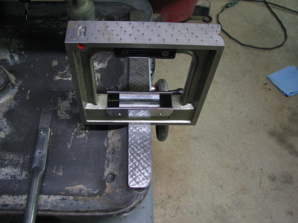
I decided to
check the table support to see if the bottom surface was 90° to
the mounting surfaces. I was surprised that I couldn't detect any
light between the vertical leg of the square and the two surfaces
that bolt to the front of the table. The support base is square
with the mounting surfaces, but the boss it rides on is not square
with the table. I wouldn't have been surprised at less than 0.001"
over a little more than an inch and a half, but 0.002" was a lot.
I needed to give this some more thought.
I tried a pivot
test on the table support bottom surface against the surface plate
and it pivoted at the center. This showed that the surface was
slightly convex and high in the center. This is no surprise as
sliding surfaces usually pick up more swarf on the outer ends than
they do in the center, and consequently the wear is greater at the
ends of the shorter sliding surface. Because I was still unsure
what to make of the measurements I taken on the boss, I decided
that I would start scraping the table support first. The support
is pretty scarred on the bottom. There are also some wear lines
that are not parallel with the bottom rectangular surface. It
appears to me that the support had been mounted cocked on the
front of the table at some point in the shaper's past. I also
noticed that the way wiper felts on the support base were worn out
and not doing their job of keeping swarf from getting between the
support and the boss. Knowing that wiper felt replacement is often
overlooked, I had purchased enough to last me quite a while. I'd
replace these once I scraped the bottom of the support.
 |
 |
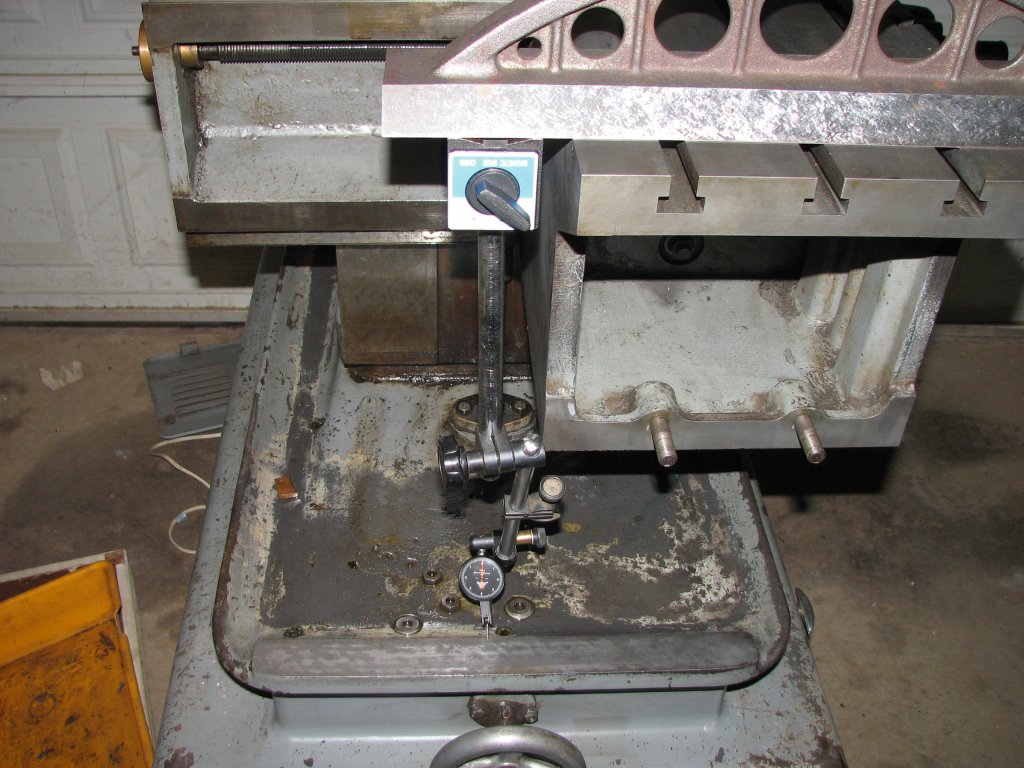
| Using
the straight edge to support the DTI, the boss appears to
be out of parallel with the table by 0.002" across the 1
9/16" section of the boss. |
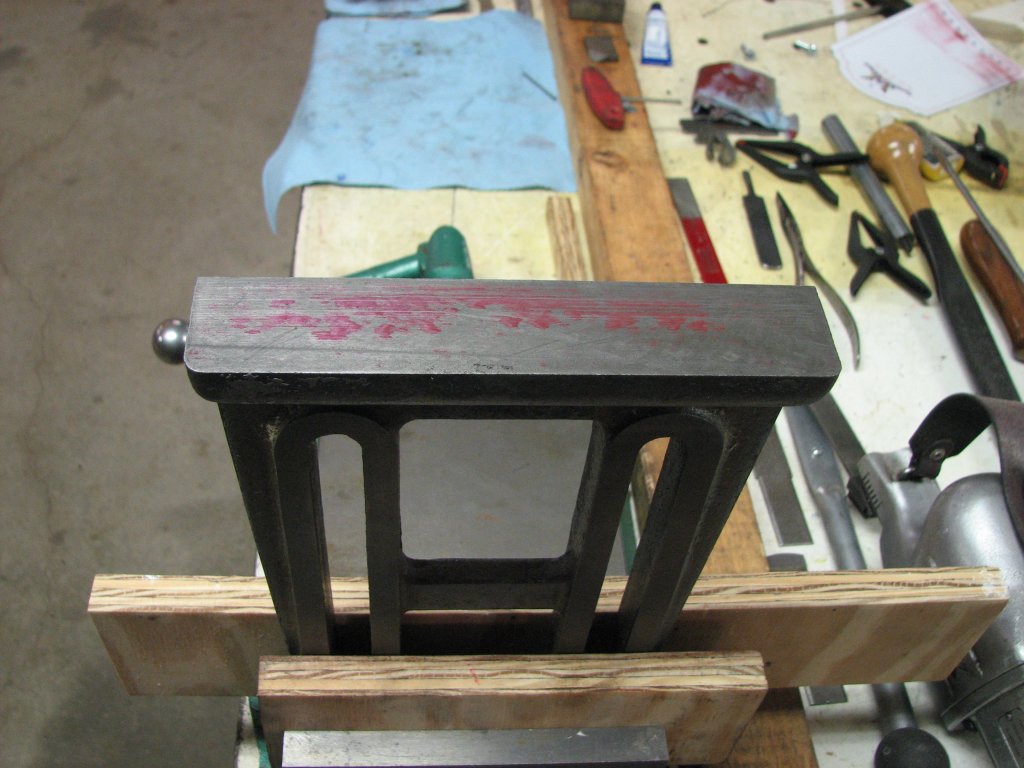
Amazingly,
even though the bearing surface of the table support is
scarred and worn, the attaching surfaces are square with
the bottom. |
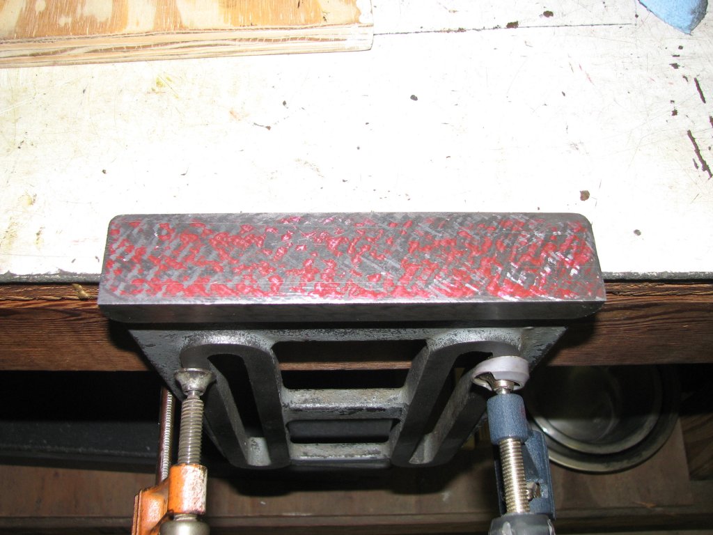
The first print
I took of the table support base showed color in the center, but
more color on one side than the other. This didn't necessarily
mean that one side is more worn as I could have just put a little
more pressure on one side while I was marking it. When a piece is
high in the center, it will rock as you try to print it. Before I
started scraping, I mounted the inked table support to the table.
I would try to wear off the print I had just taken against the
surface of the boss to see if my print matched the front to back
slope of the boss. This should confirm or refute that the table
support base is in the same plane as the boss it rides on.
However, like anyone who has tried to bring a machine into being
square with itself has found out, there is always another issue to
contend with and sometimes they don't make a lot of sense.
The table
support base is L shaped. The lower leg of the L that sticks out
has rounded corners and the side that is flush with the upright
leg has square corners. If I mounted the support with the
leg with rounded corners facing the operator, the base over-hung
the operator side of the boss by about a 5/16". If I turned the
support the opposite direction, it over-hung the inboard side by
1/4". With the rounded corners facing the ram, I could possibly
place a shim between the table and support in order to center the
base on the boss, but I am at a loss as to why this should be
necessary. Judging by aesthetics alone, I assumed that the side
with the rounded corners was meant to face out toward the operator
so the rounded corner wouldn't catch your pant's leg. If my
reasoning is correct, then there's a rather large misalignment of
the table support to the boss. As I said, it doesn't make a lot of
sense.
It has been said
that scraping is easy, but knowing what to scrape takes a lot of
detective work. The same seems to hold true for figuring out what
the machine designer had in mind.
I am trying to
play detective and am coming up with no good explanation for what
I am observing. On the somewhat plus side, the fact that the
support base overhangs the boss and leaves one side of the boss
with no contact could account for more wear on the rear of the
boss than the front, if the L shaped portion was usually mounted
facing the ram. I admit that it's only a guess, but it makes a
little more sense than anything else I can come up with.
I needed to
scrape the support base no matter what the cause of the
misalignment, so I thought I'd start with this surface and think
about the alignment of the support base to the boss a bit more.
Being only a
novice scraper, I have been doing some more reading and watching
some videos about scraping with the Biax in order to improve my
technique. After reading about how your should keep the distance
between each scrape mark about the same as the width of the scrape
mark, I realized I hadn't been doing this as much as I could. I
decided to try to slow down the speed and increase the length of
the stroke to see if I could rough scrape a little more accurately
than I had in the past. I used #2 speed on my Biax 7ELM with about
a 1/2" stroke. With the scraper angled at 45° to the long side of
the support, I moved the Biax over the length of the surface. I
ended up with scrape marks separated by spaces that were about the
same width of the scrapes. This was an improvement over my my
previous technique. It took a couple passes to scrape the color
from the first print. With each new print, I again reversed
direction and ended up with a bunch of X marks on the surface.
Slowly, I gained more bearing points. However, I found that with
the stroke speed slowed down, I needed to hold the Biax handle
tighter against my body to counteract the push of each slower
stroke. If I didn't support the Biax tightly enough, it jumped
around quite a bit.
 |
 |
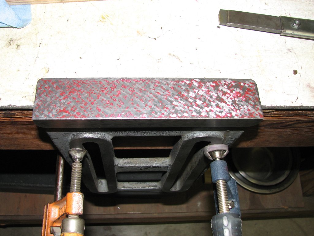
| To have
an additional way to check the table support boss being
square with the table, I decided to scrape this surface
first. |
A few
cycles with the Biax and some cuts with a hand scraper to
break up bigger points, I began to get some color across
the bottom surface. |
After a few more cycles of scraping with the Biax, I switched to a hand scraper to start working on the finish passes. I know that it is possible to finish scrape with the Biax, but I do a better job with a hand scraper. Once I was pretty close to the bearing I wanted, about 25 points per inch, it was time to relieve the center 40% by a small amount. Even though there are way wipers on the table support, in my short time of using the shaper I found that a fair amount of swarf lands on the boss that the support slides against. The swarf will get under the wipers and wear the outer ends of the support first. Hopefully by relieving the center portion of the support base, the table support will stay flat for a longer period of time. Relieving the center section involves some guess work since you cannot reliably print the area you are relieving without a specially made template. To relieve the center 40%, I cut in a cross-hatch pattern, 45° one direction, then switched directions for the next set of passes, with each scrape going the full width of the surface. I scraped four cycles in each direction without printing, while offsetting my scrapes by about a quarter inch each cycle. I tried to use the same pressure for each scrape. If I have done this correctly, when the ends of the table support finally wear down so that the center 40% starts bearing on the boss, I would like the center surface to have a nice array of bearing points. I don't know if I will achieve this, but that is my goal.
In the picture
below right, I have the first few passes of relieving done. As you
can see by the stray bearing points in the center section, I still
have to go a bit deeper. I am now beginning to finish scrape the
center section by using shorter strokes and just cutting down the
high points as marked by my camelback placed perpendicular to the
base. Printing this way is not that accurate, but it's better than
scraping blind. I am using a good deal of pressure on each stroke
to increase the depth of the relieved area. Once I get the
relieved area finished, I also need to start splitting some of the
points on the outer ends to get a little more even bearing.
 |
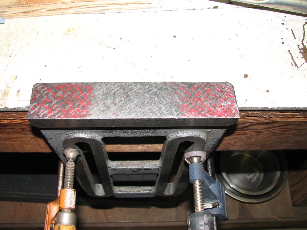 |
| A few
cycles with a hand scraper and I am starting to get some
pretty good bearing. The next step will be to relieve the
center 40% of the surface. |
The
base is 7.0" wide, so I relieved the center 2.8" (40%). I
still need to scrape a bit deeper as evidenced by the
stray spots in the center. |
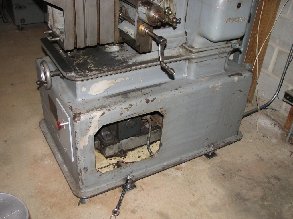
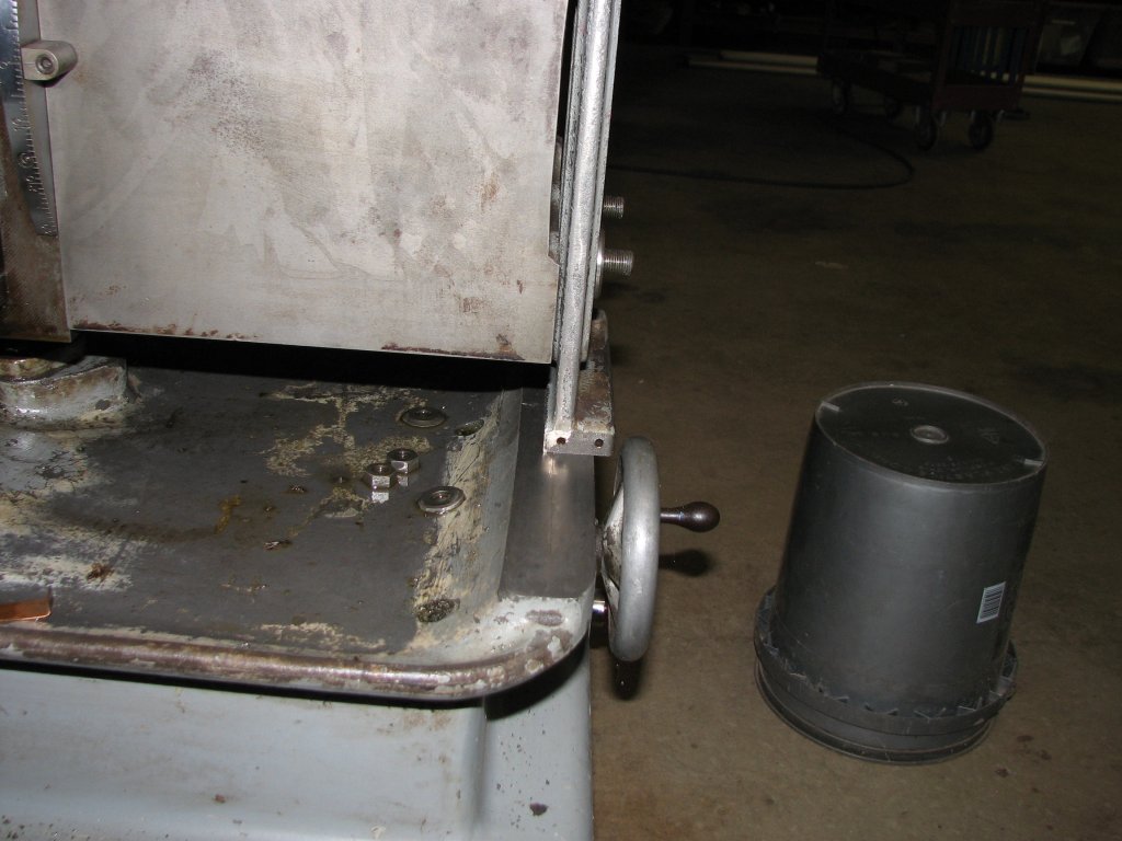
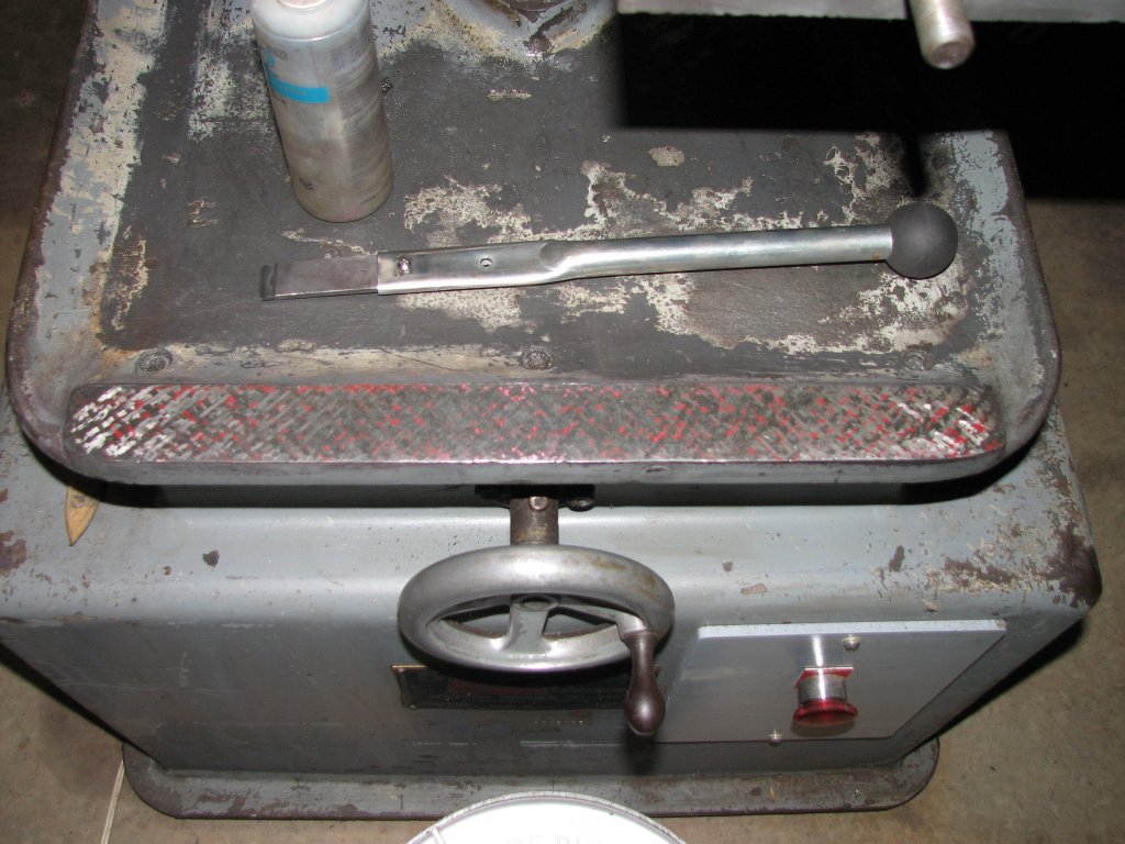
Toward the end of the evening, I decided to recheck the measurements I had taken on the boss in the Y (front to rear) axis with a level. I had seen a little too much discrepancy in the DTI measurements I had taken when I had tried to move the straight edge fore and aft on the table. I rechecked the table for being level and found that it was off by a half thousandth over the 10" wide table. While the shaper not being level, wouldn't affect my DTI measurements of the boss, getting the shaper level to gravity would allow me to use my box level to confirm the measurements I had taken with the DTI. Because the shaper didn't stay leveled over a couple week's time probably meant that the thick rubber padded I had added to the leveling adjusters were too flexible. While in the process of readjusting the table level, I noticed that I could move the level's bubble by stepping on the flange that the adjusters bolt to. I guess this confirms that the rubber pads were allowing the machine to move around a lot more than I wanted. I needed to fix this before I went any further.
 |
 |
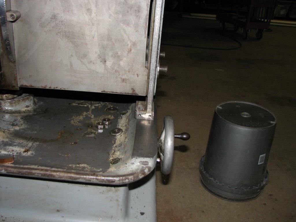
| The
rubber pads have been removed from the shop made height
adjusters. I'm now thinking that I should have wider
adjuster feet and secure them to the cement floor. |
It is
easier for me to level a machine by leveling diagonally.
Having the level aligned with the adjusters makes it
easier still. The tape marks allow me to repeat my level
placement. |
 |
 |
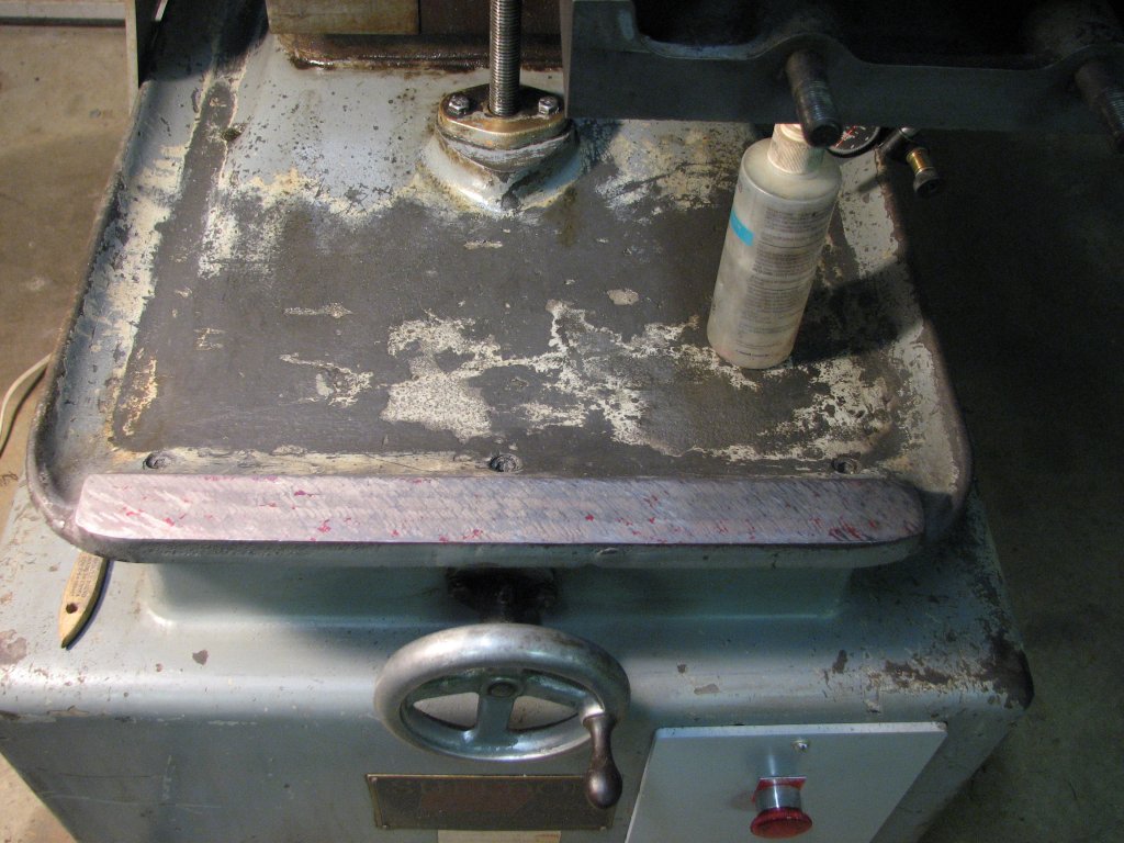
| Table
support sitting on the boss in the direction that I would
think to be correct except that the front of the support
base overhangs the boss |
If I
reverse the support, it overhangs the rear of the boss,
but not by as much. While I can correct for this, it
doesn't seem right. |
 |
 |
| I
made a shim from some stock I had on hand and added a
1/16" thick washer behind each leg to get the support
centered on the boss. . |
I
found a picture online showing another Sheldon shaper
with the table support overhanging the boss. Apparently
this issue wasn't limited to mine. |
 |
 |
| Since
I forgot to take a picture before I started scraping,
here's a shot after a few cycles with the Biax and a
couple cycles with a hand scraper. |
The
boss is still about 0.001" high on the left. I will now
scrape enough cycles to get the surface smooth enough to
map out the slope accurately. |
 |
 |
| Step
scraping the table support boss to remove one
thousandth inch of slope over 16.5". Click image for
animated gif (2.5 megabyte file size). |
After
the step scraping passes, I went from a decent points
count to next to no points at all, but the boss is now
pretty much level with the table. |
 |
 |
| After
one pass with the hand scraper, I am beginning to
see where my high and low areas are located. I have
some more scraping to do. |
Double
checking the plane of the support boss against the
plane of the table on a leveled shaper. I couldn't
have asked for a better reading. |
 |
 |
| With
the level set across the 1 9/16" boss, some
inaccuracy is expected, but the level shows that
this plane is pretty close to level with the
table. |
Another
couple of cycles with the hand scraper and I am
beginning to see some color across the whole
surface. Finish scraping is the next step. |
 |
 |
| I am pretty close to done scraping the
boss. I have a few sparse areas and will scrape
another pass or two, but am pleased with my
progress. |
Taking a test cut. With one side of the
CI block surface ground, I planed the other
side. The planed surface came out pretty close
to parallel. |
| Shaper
1 |
Shaper
2 |
Shaper
3 |
Shaper
4 |
Shaper 5 |
Shaper 6 |
Shaper 7 |
Shaper 8 |
Shaper
9 |
© Fager October 14, 2015