
|

| September 27, 2005 | |
 |
About
4
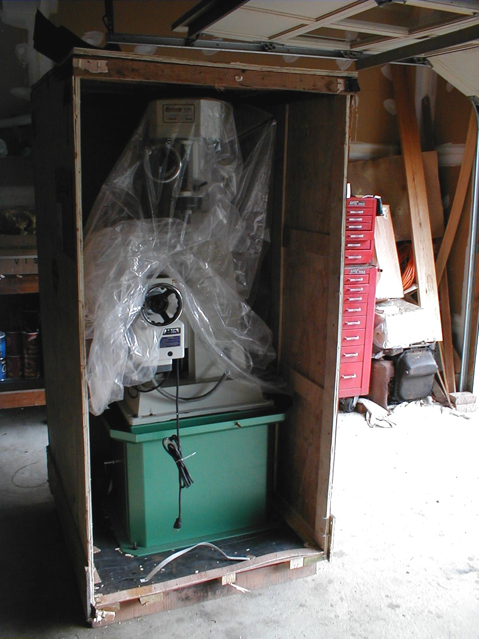
PM on September 16, the truck finally arrived with the new
mill. I had paid an extra $75 to get it
delivered by a
vehicle with a lift gate and pallet truck so that the 950
pound crate
could be lowered to the ground and pushed up the driveway
into the
garage. The extra $75 wasn't a problem, but trying
to get it
setup with the trucking company was a bit of a pain and
ended up taking
quite a few telephone calls. You'd have thought that
Grizzly had
gone through this enough times to make that part of the
purchase less
of a hassle - or maybe I was the only person to have
trouble, but I
finally got it worked out. The mill was wheeled on to the lift gate and swayed back and forth a few times as it was lowered to the ground. I just stood back and watched as there was no way I would be able to do anything if it started to fall. The lift gate hit the street with a bang and the trucker seemed as glad as I was that the crate was safely down. |
 |
Between
the
trucker, his helper and me to pull and push, it wasn't too
much of
a chore to get the crate into the garage. It even
cleared the
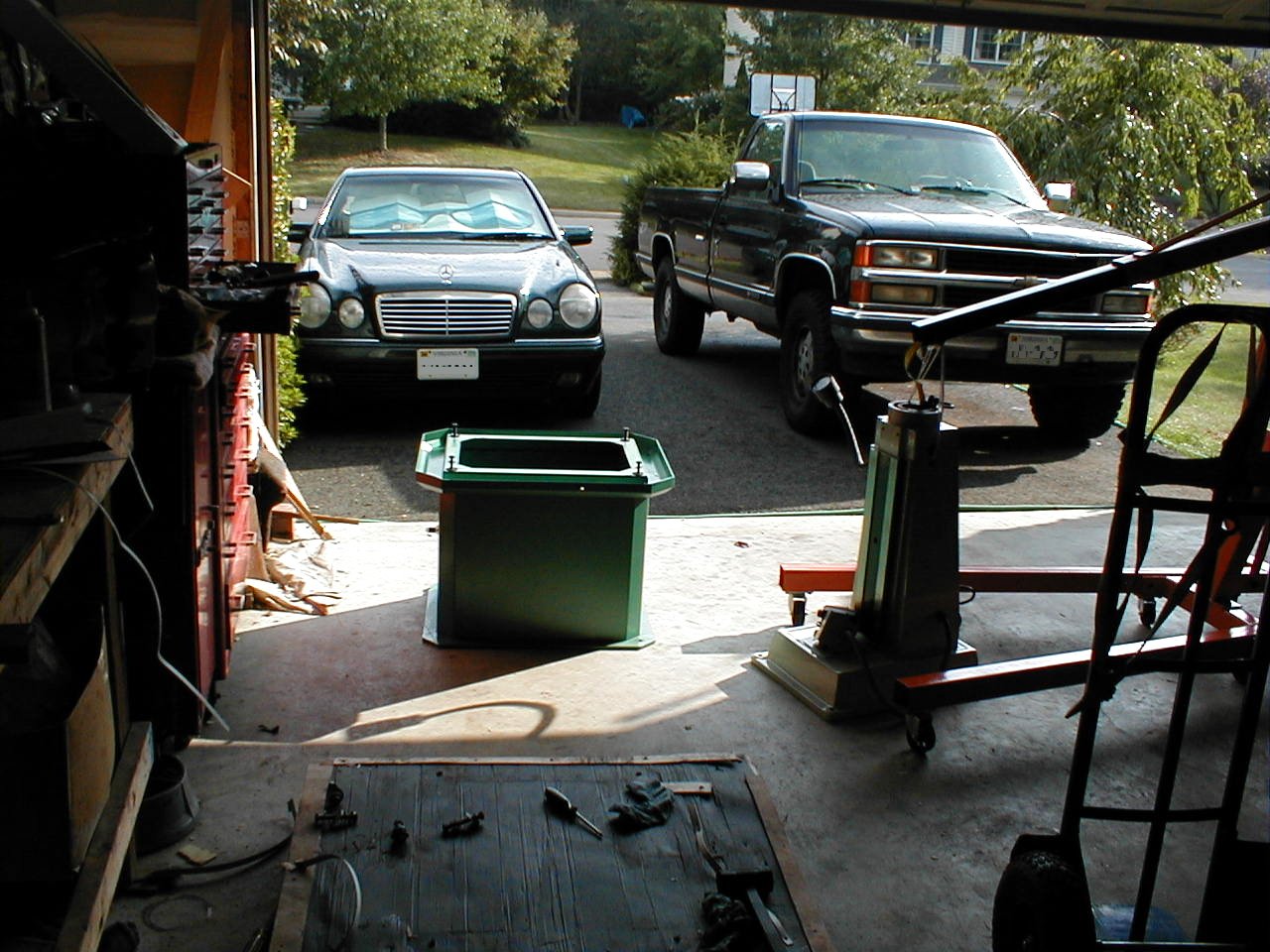
garage door by about 2 inches. I grabbed my big yellow screwdriver (~3 feet long) and pried open the front panel of the crate so I could open it and check the machine for damage. I had been warned by one of the guys on the 6x26 Milling Machines Yahoo group to pay special attention to the two crank-wheels that would be on the floor of the crate. Sure enough, when I opened up the paper wrapped wheels, both had some rust on them. I noted this on the trucking bill and grabbed an end mill holder and slid it into position in the spindle, then tightened up the draw bar. This was another check that was recommended to me as there were a few mills that had been shipped with spindles that were not properly machined. The spindle on mine was fine. After signing off on the package, it was mine. I was pretty excited. This mill had been a long time coming and I had researched this purchased for so long that I had wondered if it would ever see it. Now, phase two had begun. I would need to strip the mill down far enough that I could move it from the garage, around the house, over the lawn, through the back yard and into the sliding glass doors on the walk-out basement. I was hoping that I would just need to pull the head and table. |
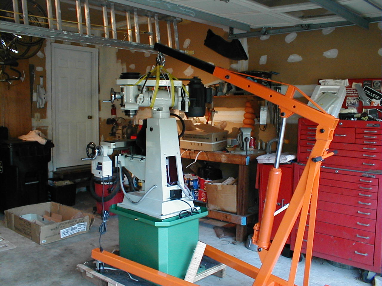 |
Off to the local Harbor Freight
store to get a fold-up two ton engine
hoist that was on sale
for $150 and a big, pneumatic-tire equipped hand
truck. I broke
down and also bought some other
stuff while there. There is more stuff at Harbor
Freight that I
don't need, but "might just need" than I can take. A
lot of the
stuff is of questionable quality, but the hoist was well
worth the price. The first step in stripping down the mill was to open the electrical box and disconnect the wires for the motor. I drew up a quick sketch of the wiring so I wouldn't have to try and remember where everything went. I used a nylon tow strap and wrapped a few turns around the turret, head and motor,each time passing through the hook on the end of the engine hoist boom. A few wraps of some nylon cord to add a little tension to keep the head level, then unscrewed the three acorn nuts that held the turret to the column. With the engine hoist's front legs up on the pallet, I lifted the unit up until I had a couple of inches of clearance. I was planning to just roll the hoist back until it reached the edge of the pallet, then drop it a inch or so to a couple of 2X4 blocks, then on to the floor of the garage. |
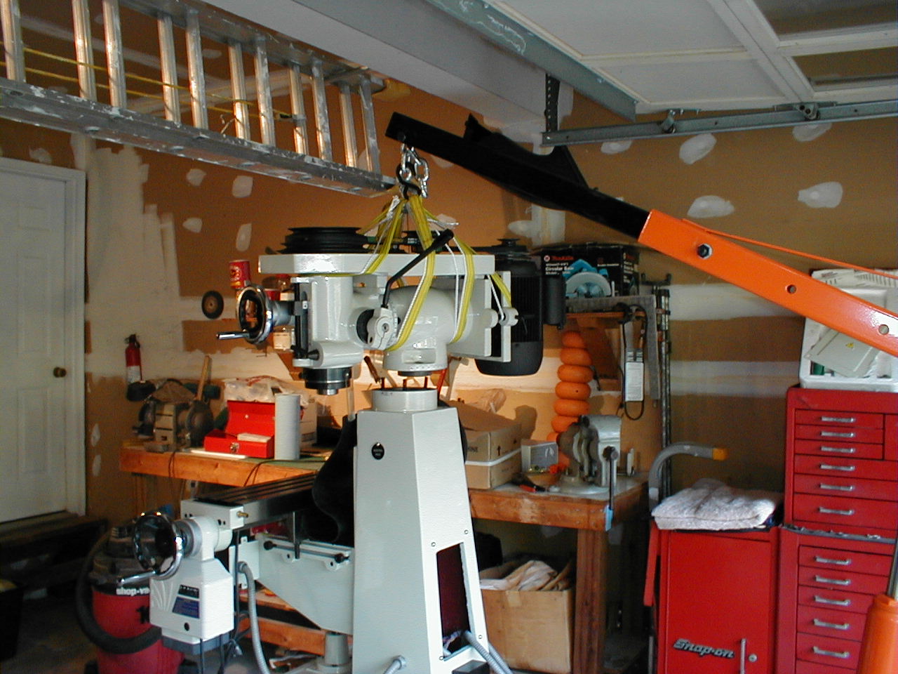 |
Unfortunately,the
thin
wood on the floor of the pallet couldn't hold the weight
of the
engine hoist and head assembly and one of the casters
broke through the
plywood. Oh crap, I'm in trouble now! A yell to my wife got her into the garage and within a couple minutes we had also enlisted the help of a neighbor. Between the three of us, we were able to lift the front legs of the hoist out of its hole and on to the garage floor. With sweat pouring off of me, I thanked all concerned and looked at the head assembly in amazement. Dam, this thing is heavier than I thought! If I had to do it over again, I think that a couple of 2X4s shoved under the pallet with a piece of plywood or two to take up the space, would have prevented the engine hoist caster from breaking through. Live and learn. |
 |
One of the modifications that
I may be performing on this mill is to install a "riser
block" between the
top of the column and the
turret. I have seen them done in both 4"and
5". I'm pretty
sure that I will be making
a 5" so I will be able to raise the working height enough
to get over
my rotary table and work on larger pieces, but I will do
some set-ups
and see exactly how much more room I will
need. I
took a break from the moving to sketch a
riser block and transfer the measurements of the turret
and the column
top to my drawing. It looks like a pretty straight
forward piece
to machine using the rotary table. The next piece to come off was the table. This comes off by removing the hand wheels on the Y axis, the power feed on the right side of the table, a circlip on the same side and a few spacers and a needle bearing race. Finally, remove the gib adjusters and gib. Once the table ends are off, it is a matter of sliding the table to the right until the dovetail of the table clears the saddle, then lifting straight up. |
 |
I
don't have to
tell you that the cast iron table is heavy, but I will
anyway.
It's heavy! Unless you're built like a power-lifter,
keep it
close to your body and have a place cleared to set
it. Boy, I'm
going to be sore tomorrow! After removing the saddle, I foolishly tried to slide the hand truck under the base and move it. No chance! So we move on to removing the knee. This is easiest if you remove the three bolts that hold the vertical lead screw to the base and the connection at the knee. Once I had the screws out, I was very dismayed to find that the pair of bearings at the top of the screw felt like crap. Crunchy! I was about to mark these on my list to talk to Grizzly about replacing when I decided that it wouldn't hurt to clean them first. I used some brake spray as solvent. Within a minute,the bearings were as smooth as glass. The protective grease had just hardened and was being ground up between the balls of the bearings. |
 |
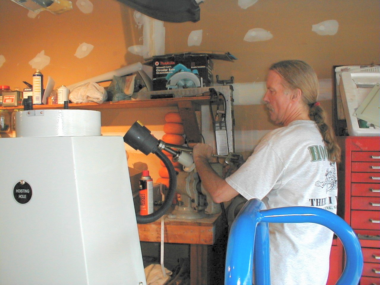
Once
I had both the bearings cleaned -
without removing them from the screw- I used a bearing
"cheater" (a
tube that fits on a grease gun that has been flattened to
a thin
semi-circle) to pump grease between the races and
balls. This
could be done by hand,but is much quicker and less messy
with the tool. Once I was down to just the column and the base, I again tried to move it. No go. Oh well, only 4 more bolts to go and it is completely stripped down. So there it is. Only 24 hours since it was delivered and it was stripped to its parts on the garage floor. Between using the wheelbarrow for the head assembly and the hand truck to move the base and column, it all ended up in the basement and I began to reassemble it. Since the mill had been painted after being assembled, there were a few paint chips where I had to disassemble parts, but I am not too concerned by this. If I get real energetic, I may find some paint that matches and do some touch-up. It turns out that beige appliance paint is a very nice match. Frigidaire brand was what I had. |
 |
On
the way back up, I took my time and ran taps through all
of the
threaded holes to make sure that the threads were
clean. I also
used some anti-seize on the threads to keep them from
seizing if
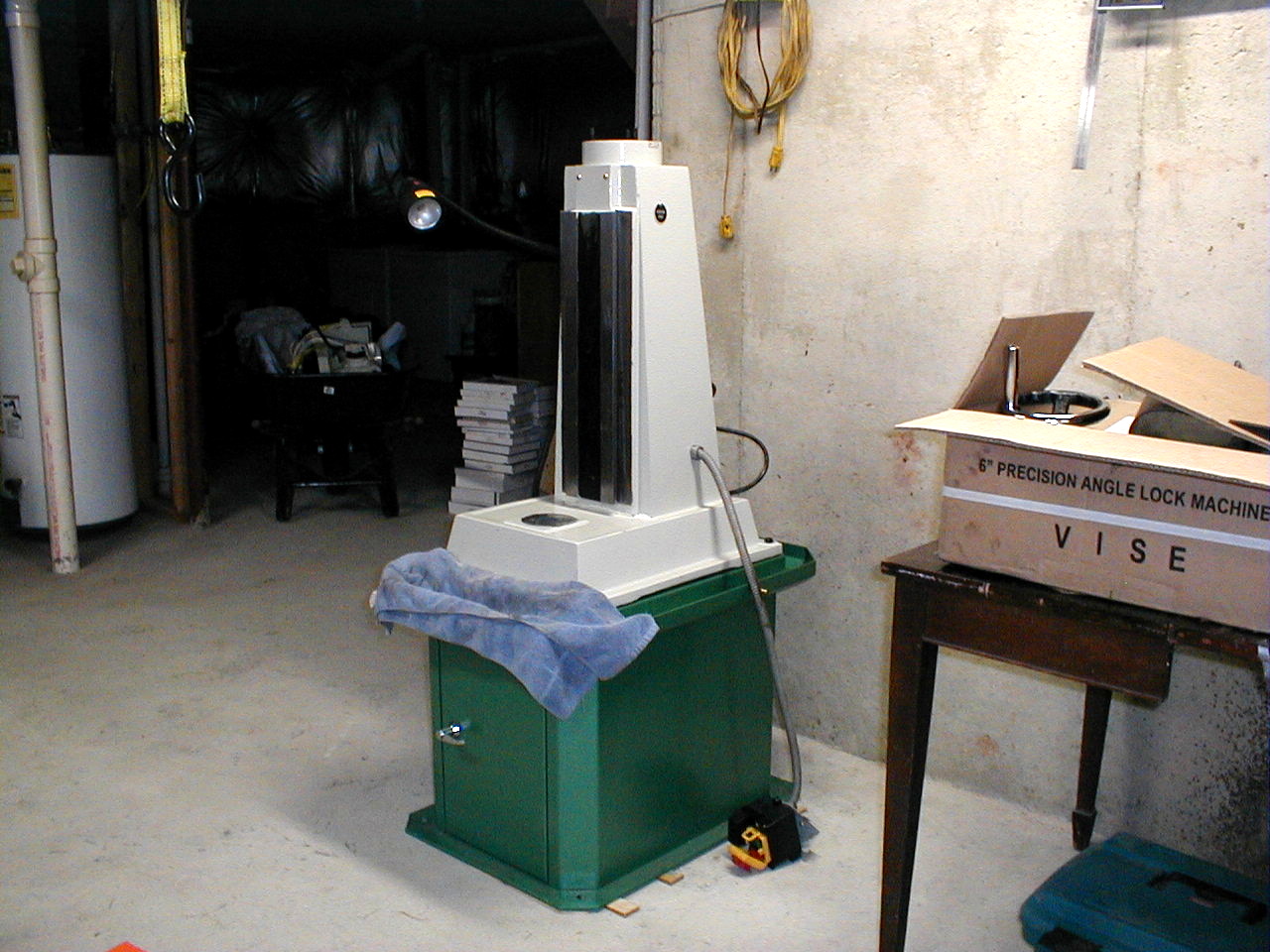
moisture should get in. Using
the engine hoist, I placed the column back on the base and
torqued down
the bolts. I made up a little sanding block and
cleaned the
surfaces of the mating parts and applied a thin coat of
grease between
the pieces to help protect them from rusting. For the time being, I have leveled the base with some wooden shims. I haven't decided if I will fasten the mill to the cement floor or whether I want to build a movable base with casters that will pivot out of the way when not being moved. I have seen a very nice design using 3"X2" boxed steel that has casters and leveling pads that would make it very easy to move to a new location. |
 |
Since
I doubt that I
will be in this house forever, I am leaning toward making
it somewhat
portable. With the amount of equipment I am
acquiring in the
basement, I don't even want to think about a possible
move, but I guess
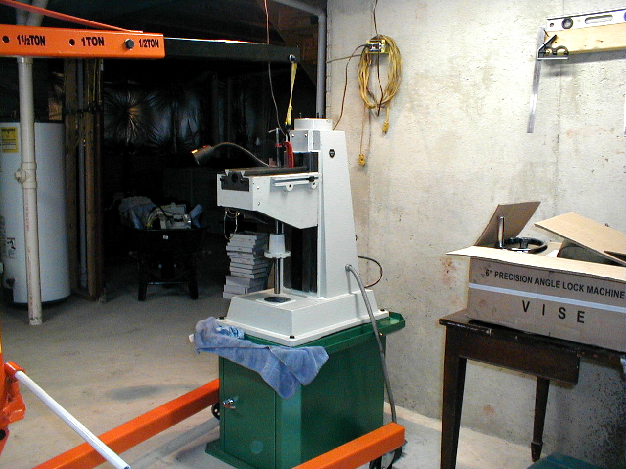
that it is better to plan for the future. - I ended up
going with Enco
adjustable machinery pads which made it very easy to level
the mill. Next, the knee gets lowered into place. The knee is not too heavy to lift, but to try and lift it AND align the dovetails to get it to fit is a little too much for one guy. The money spent on the engine hoist made what could have been a hard job, easy. The casters on the hoist moved smoothly on the basement floor, which made the alignment of items like the knee, "a piece of cake." |
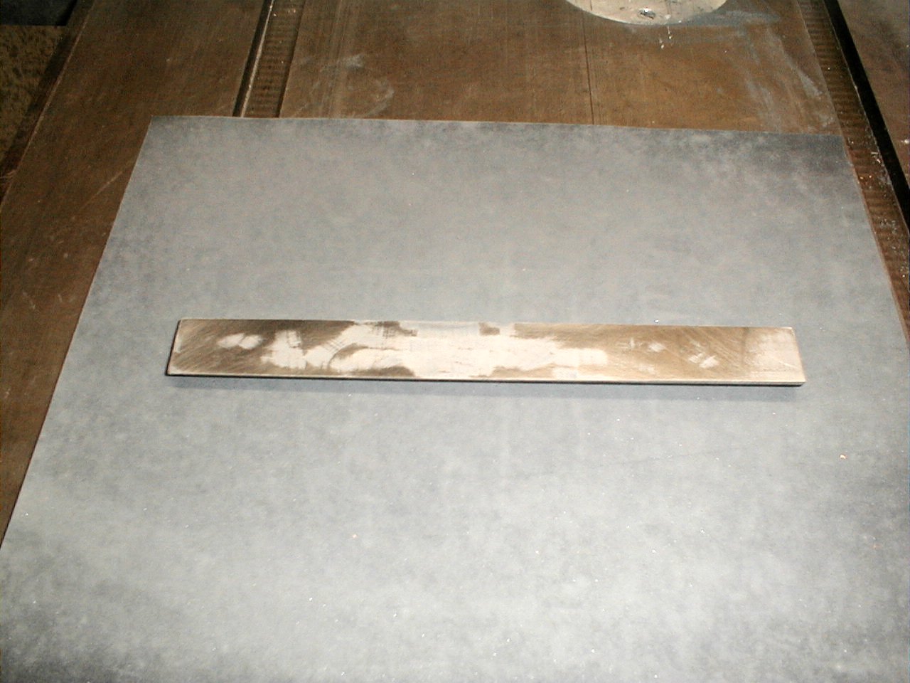 |
With the knee in place, it was
time to turn my attention to the knee's
gib. It is a hand scraped piece made of cast
iron. The
finish was pretty far from being flat. I had read
that it
would be good to have at least a 70% contact between the
gib and the
ways so that there was some room for lubrication.
The center of
the knee gib was low by a few thousandths and as you can
see in the
picture, the center of the gib looked the worst after a
few minutes of
lapping. I continued lapping with progressively
finer grades of
wet/dry paper until I had a pretty nice finish. I
cleaned the
ways and dovetail, then lubed them up and installed the
gib and two
adjusting screws.
Eventually I will
get in and re scrape the ways and gibs, but that's not
part of my
immediate plans. This procedure was repeated on the other two axes. Hand lapping takes some time, especially if you are starting with something like a 300grit paper, but trying to speed up the process on my power sander was discarded as it is too easy to take off too much material. So it was back to figure "8" patterns on a whole sheet of paper on top of my cast iron table saw table. That old Craftsman saw table may be ugly, but the table is pretty flat and solid as a rock. To quote an old saying,"they don't make them like that any more." |
 |
The
attention to detail is an area where the inexpensive
Chinese equipment
is not as good as their Japanese, Taiwanese, European, and
American
counterparts, but if you are willing to take the time, the
basics are
all there and it is just a matter of some TLC to tighten
up all of the
specs. Before I started lapping the gib, there was about 0.025" lateral movement in the knee and there were loose and tight spots over the entire range of movement. When I was done lapping the gib, I had reduced the play to about 0.007 with a pretty constant smooth feel while cranking the knee up and down. No doubt that will grow a bit as things wear in, but nevertheless, it is quite an improvement. The difference in smoothness after cleaning and repacking the bearings on the top of the Z (vertical) lead screw was - as one would suspect - nothing short of amazing. |
 |
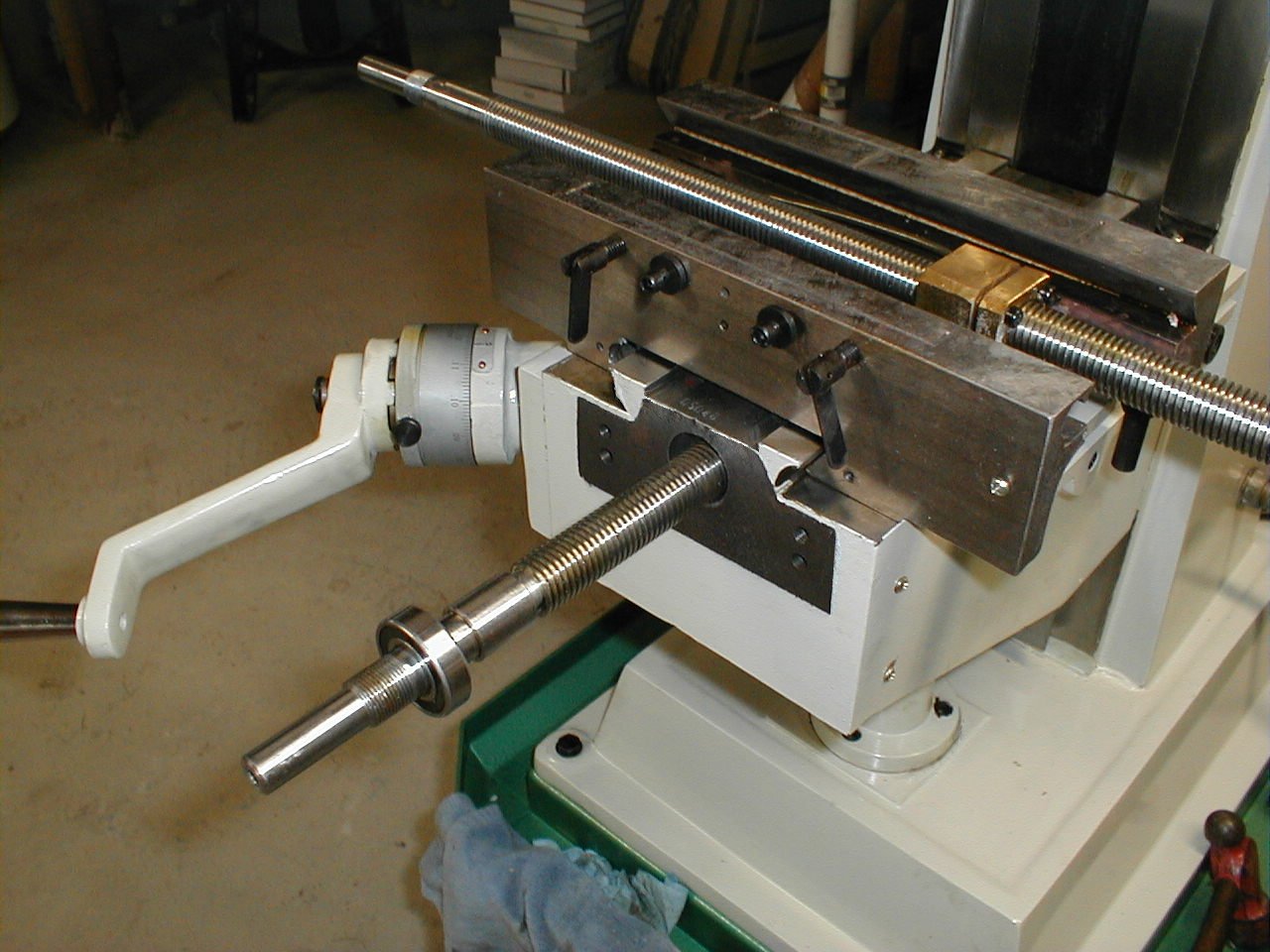
With
the knee back together and feeling good, it was on to the
X and Y
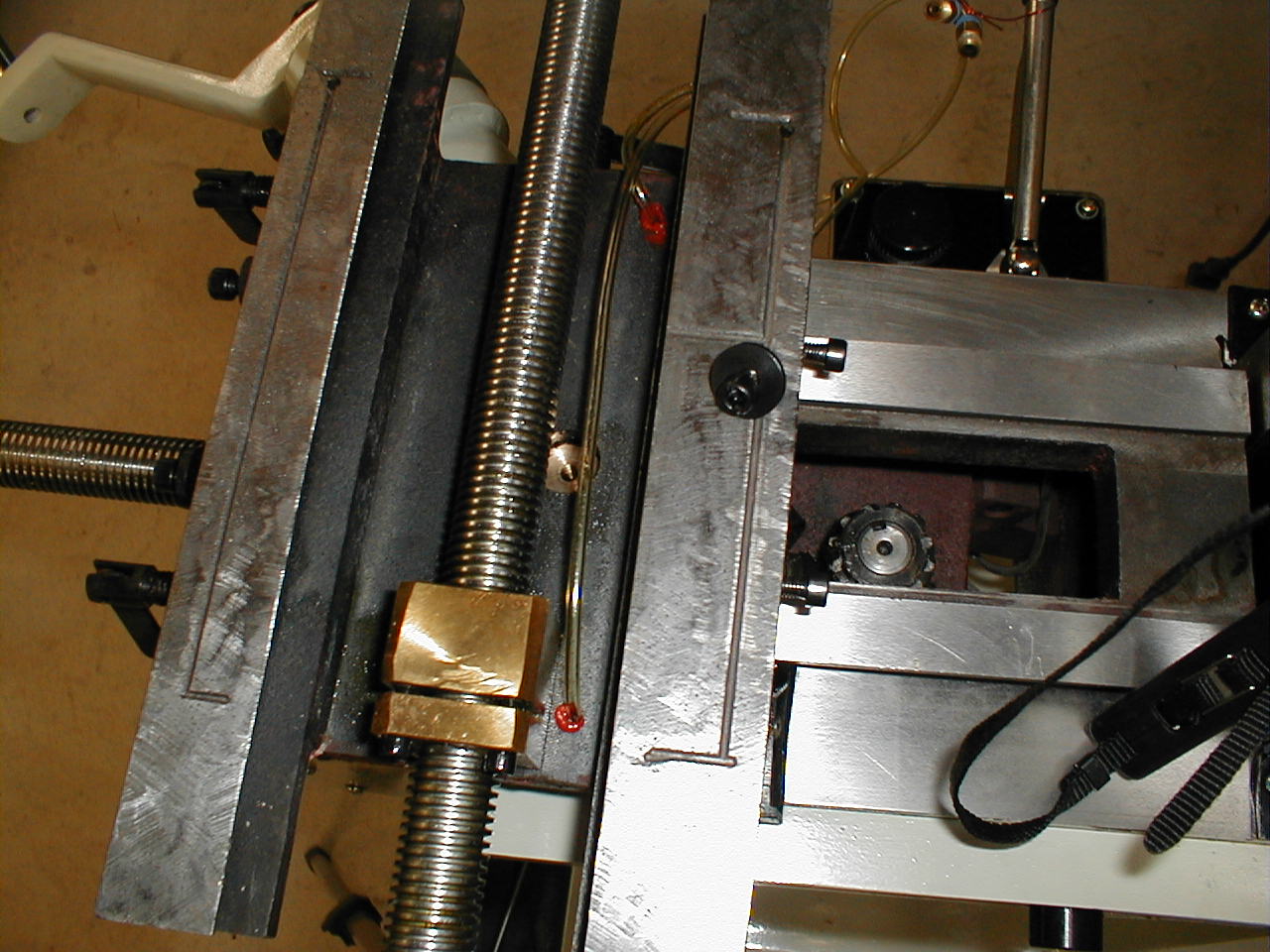
axes. One thing that I was not real impressed with
was the
backlash adjustment on both the X and Y axes. It is
accomplished
by a slot being machined into the brass lead screw nut
with a couple of
cap screws to pinch the nut on the lead screw. (See
the image
below.) Before disassembling the mill, I checked the
actual
measurements against the sheet of readings provided by the
factory. Backlash was not one of the provided
measurements;however, I checked and noted backlash for all
three axes,
so I would have a guide to
assemble to. The X axis was the worst of the three,
with
0.011". |
 |
After lapping the gib and
cleaning up the dovetails, I mounted the saddle and checked the X axis
backlash.
It was easy to bring it to a very smooth 0.009",but as soon
as
I tightened up the two cap screws to try to remove more of
the
backlash, the nut seemed to bind on the lead screw.
I went
through this a couple times with no improvement until I
surmised what
was happening. The slot in the nut was allowing the
nut to pinch
the threads, but because there was a slot instead of a two
piece nut,
the pressure on the lead screw was uneven with more
pressure being
placed on one side of the nut than the other. I'm
going to need
to fix this as soon as the mill is together. The mill is equipped with a "one-shot" lubricating system. When I first broke open the crate, there was oil all over the base of the mill. At the end of the first day's work, I had noticed that two of the clear plastic lines that kept the X axis oiled were just stuck into their holes. The remainder of the lines had screw-in fittings. I thought that the lines that were not screwed in were probably the ones that were leaking, so I used a little high temp,General Motors orange silicone sealant to seal the tubes to the holes. |
 |
The
next day I filled the lube tank about 1/4 full before
I broke for lunch. When I returned, the tank was
empty and there
was oil all over the place. It appears that the
oiler is
siphoning the oil from the tank and it leaks out from all
of the oiling
points. None got past the two lines that used
sealer, but it did
come out below the holes where the oil exits to keep the
ways
lubed. I will have to look around to find a check
valve that will
only pass oil when I press the pump handle and pressurize
the
lines. For now, I will keep the tank empty and lube
the ways with
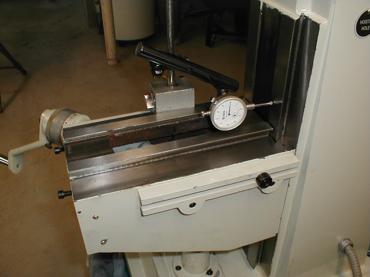
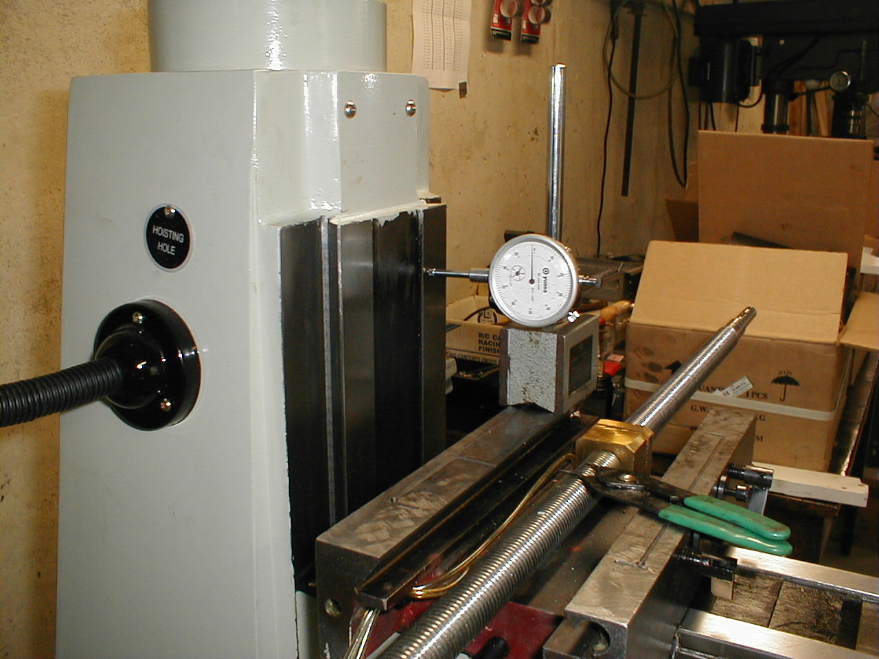
an oil can. While I am on the topic of future plans, another project, no, make that purchase, is some new adapters for my dial indicator. I purchased the dial indicator decades ago,primarily to measure run-out on brake rotors and for measuring the spring tension on Mazda rotary engines. It came in a heavy duty plastic case, which is probably why after twenty-some years, it is in great condition. I can see that it will now have a "second life" in the workshop. |
 |
I
have already used it more in the past
week than I have in the past ten years! I need to
find a couple of
adapters that will make it easy to use it for aligning the
machining
vise, tramming the head, and general set-up work. In
the
searching I have done so far, I see lots of magnetic
bases, but no
shafts and right angle adapters. I'm sure they're
out there, it's
just a matter of finding them. It would seem that in
getting a
mill, there are many, many accessories that I will
need. It looks
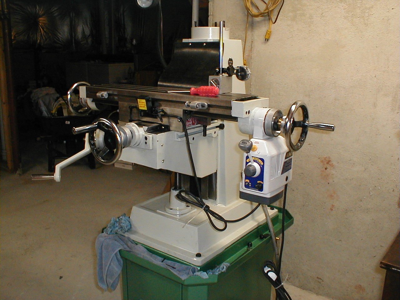
like I may need a second job to support this new "habit." Anyway, more measuring and more assembling. With the table on and the end-play adjusted on the table lead screw, I had my first chance to try the Y axis power feed. It works as it should and will be a nice feature. The power feed main gear rides on a needle bearing and is smooth as silk. Nice. Finally I was getting close to having the mill up and running. |
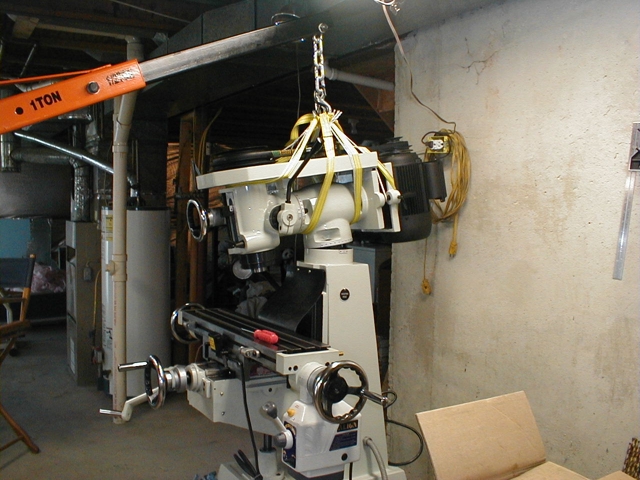 |
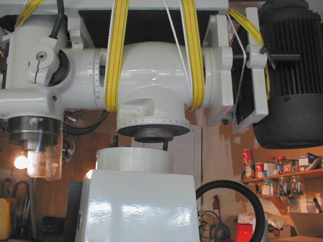
Once
more I grabbed the engine hoist an lifted the head,
turret, and motor
assembly out of the wheelbarrow and set it atop the
column. After
some more measuring, I had the head assembly aligned.as
close to
perfect as I could get it. I rewired the electrical
box and
finally plugged in the two power cords and hit the main
switch. Success! After making a couple cuts to make sure that the alignment was true, I rechecked the backlash on the X axis. It was horrible. I fired up a computer and started looking at different styles of anti-backlash nuts on the web. I found that the majority were made from two pieces that either screwed together with a shim or spring between them. This would allow the pressure of the nut on the lead screw to be constant for the full rotation of the thread as opposed to the current pressure on one side and no pressure on the other. |
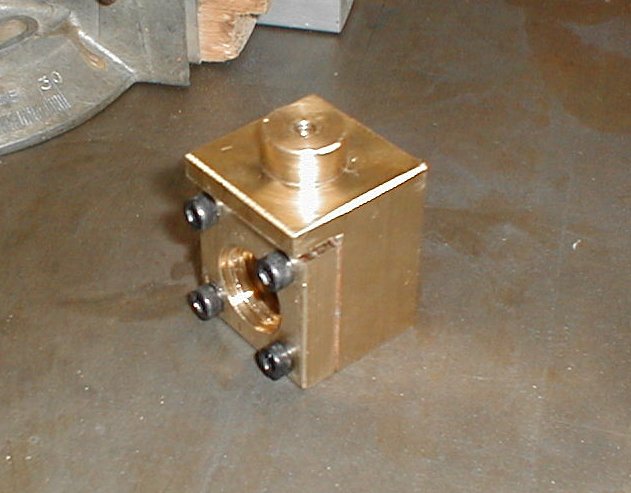 |
I reasoned that if I cut the slotted
section off, drilled and
threaded a couple more holes for an additional two cap
screws and made
a shim of the proper
thickness
(I.E., to put the right amount of "pinch" on the
threads),it would work
better. To do this, I would either need another nut,
or remove
the existing nut. I could remove the existing nut
and still use
the mill if I locked the X axis and worked only with the Y
axis.
I would extend the slot until I cut the nut into two
pieces. This was the first "real" cut I made with the mill and even though I only had the y and z axes to work with, it was sweet! I'm going to love working with this tool! The end mill cut the material like butter and soon I had a two piece nut with a copper shim to adjust the pressure on the lead screw. I decided that instead of clamping the threads together, I would shim it so that the force would be toward the outside - an expanding, rather than pinching force. I finished the new nut, reinstalled it on the lead screw and rechecked the backlash. 0.002" and no binding! After a couple of days, this has grown to about 0.004" and seems to have stopped there for the time being. |
 |
Of
course, the backlash will grow as the threads on the nut
wear, but the
adjustment is pretty easy and can be performed by removing
the two cap
screws that hold the hand wheel and lead screw assembly
onto the saddle
and adding a new shim. For adjusting in small
amounts, a piece of
aluminum foil makes a nice shim. I reassembled the table to the saddle and measured the backlash on the Y axis. With the clean-up, lapping of the gib and touching up a couple of burrs on the long table lead screw, it came in at just under 0.005". I decided to hold off on modifying the Y axis nut until I needed to adjust for wear. After some searching on the web, I have found a couple designs for adjustable lead screw nuts that will allow me to adjust without using shims. I think that this will be a project for the future unless I decide to convert to CNC. |
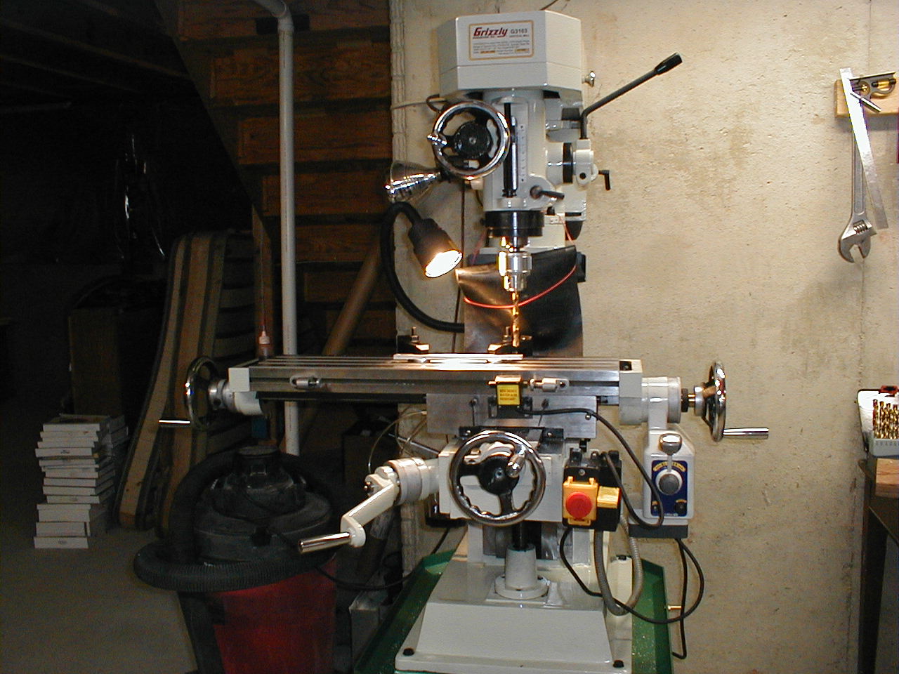 |
I
have
seen some shots of a
Grizzly G3103
that has been converted to CNC with ball screws and it
looks
nice. Whether I go that route or not remains to be
seen, but it
is fun to ponder. Another possibility - and a much
cheaper
project - is to mount up a digital readout (DRO).
There is a
pretty neat do-it-yourself setup using Chinese scales and
a controller
box by ShumaTech. There
is
also a Yahoo
group devoted
to assembling the project. I have read about half
the posts in
this group and am getting pretty close to ordering the
circuit board
and scales. However, before I start a new project, I
really need
to clean up the workshop. I picked up some shelving,
which will
give me a place to put all of the heavy stuff for the mill
and I still
need to get some pegboard for the items that can be hung
up. In
the near future, I'll not only have a working mill, but a
clean shop as
well. What a treat that will be! |