
|

 |
 |
| Well,I
thought it was a good idea to use the wedges, but it introduced a bow in the table. |
I was getting pretty close to being completed with this one way, but now I have to rescrape the dip out of the center. |
With the 47" table, 47 X5 /
9 = 26.1. This means the distance between the 2 supports
will be26.1". This will put our supports approximately 10.45
inches from each table end. With this setup, I can now minimize
the possible sag. All that's left is to do is to scrape the ends
to match the dip I scraped into the center of the ways when I
inadvertently raised the height of the center with the wedges.
Double darn. This not only hurts my pride, but also means that I
have to take more metal off of the ways than the bare minimum I was
hoping for. Since the relationship between the flat and inverted
V ways is fixed, I will also need to scrape more material off of the V
ways to keep the table from tilting in the fore to aft (Z axis).
Note: The Z axis is the axis that moves parallel to the spindle axis
and the spindle on this grinder is horizontal, so the Z is the
horizontal and X is the vertical axis. This is the opposite from
a vertical mill.
I had no sooner set the supports
up under the grinder's table on my work bench when I happened to glance
at the surface grinder. Wouldn't you know that the two Z axis V
ways that support the saddle appeared to be positioned using the Airy
formula. It certainly made sense that the designers would have
wanted no sag in the table, but I needed to check it out myself. I
grabbed a tape measure to check. The two V ways were as close to
10.45" from the ends as I could measure with my tape measure.The
correct position for supporting the table was staring me in the face
and I still didn't think of using it.
Week of March 15, 2008
This great revelation happened on Sunday the 9th. It's now
Saturday the 15th. I've been scraping every afternoon this week
for a few hours and I'm still not back to where I was in terms of
groupings of high spots on last Sunday. I only had to lower the
ends by a few ten-thousandths,but to do this I had to go back to using
a "normal" spotting technique. This is where the straight edge is
blued and layed on the ways so that the blue is transferred to the
ways' high spots. I find that this method of spotting works much
better for getting the ways flat. Once the ways are showing color
over the whole surface, I switch to bluing the ways and using the
straightedge to rub off the color on the high points, which lets me see
the individual silver high spots easier on the blue background.
Scraping is a rather slow process,
especially when it is being done by me. I have a bad habit of not
taking deep enough cuts and have to remind myself to cut deeply when I
have a lot of stock to remove. A lot of stock can be a half a
thousandth of an inch if you are only removing a hundred-thousandth of
an inch per cycle. Since I need to work on lowering the ends of
the table's ways and my straight edge is shorter than the surface I am
scraping, it is necessary to print and scrape the surface in
shifts. As I said in the first installment, I print and scrape
the center, then the left end, then the right. Because I need to
lower the ends by a couple ten-thousandths, I'll use a shortcut to help
me to remove metal more quickly. That shortcut is using a file to
assist me in removing stock.
 |
|
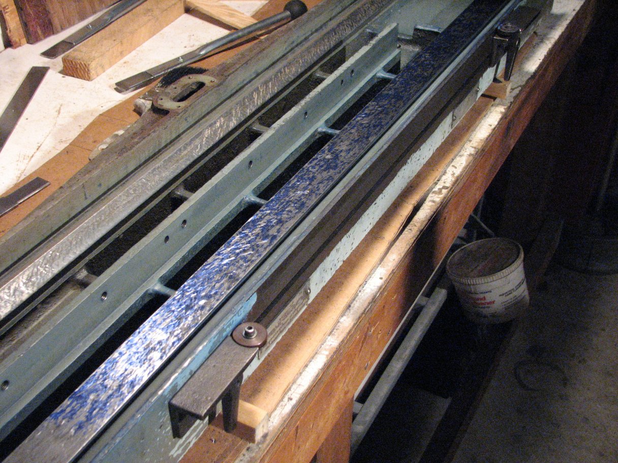
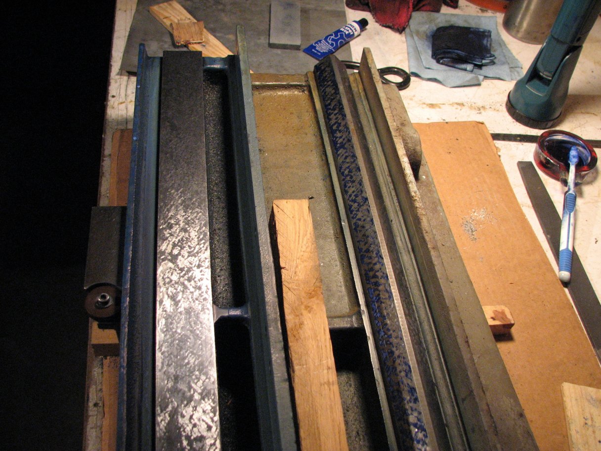
| Using
the normal spotting technique of blue on the straight edge and
transferring it to the way, I continue to mark and scrape the bow out
of the way. As can be seen by the even distribution of metal
colored areas, the way is pretty flat. Now it's time to scrape for a
better surface quality. |
|
After I've scraped the center
36 inches, I now have about 5½ inches on each end of the ways
that didn't get scraped in the first pass. I blue up the straight
edge and set it on the ways with about 2 inches overhanging the end I
plan to work on. Because the ends are high, the print shows high
spots near the end and doesn't show any more high spots (very dark
color) until about the center of the ways. I only scrape the end
high spots. I don't touch the marks near the center. It
does make sense not to scrape the center of the straight edge until the
whole of the side being worked on shows high spots, but I always have
the temptation to work on all high spots I see. After I scrape
the high spots on the end, I grab my 15inch mill file with its handle
removed. This file is slightly bowed lengthwise. I
turn the convex side down and I lay it flat on the ways - well actually
it isn't flat, it rocks a little. With downward pressure on the
center of the file, I make a few cuts over the areas I have
scraped. If you choose a file that has a nice bow to it, you will
be able to remove metal from only the areas that have been scraped
without cutting the surrounding areas. Since the teeth of the file
act like multiple scrapers, a couple passes of the file cuts much more
metal than a couple passes of the scraper. By only using the file
on the area I have scraped (the high spots), the chance of removing too
much metal or metal from the wrong area is lessened.
I now have high spots over the
entire center 36 inches of the ways. I have the left 5½
inches scraped very close to level with the center 36 and the right end
is still a tenth or so high. Tomorrow I'll return to working on
the right side..
 |
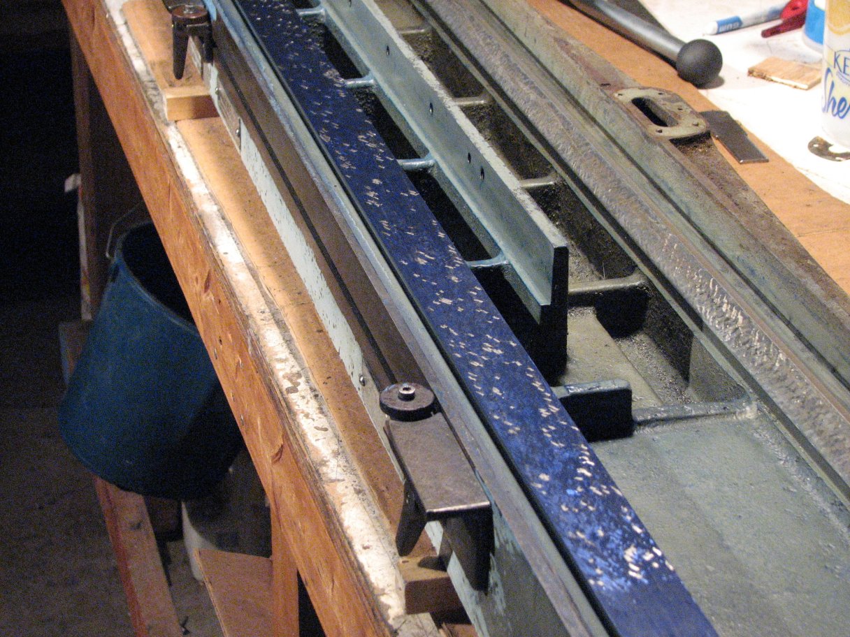 |
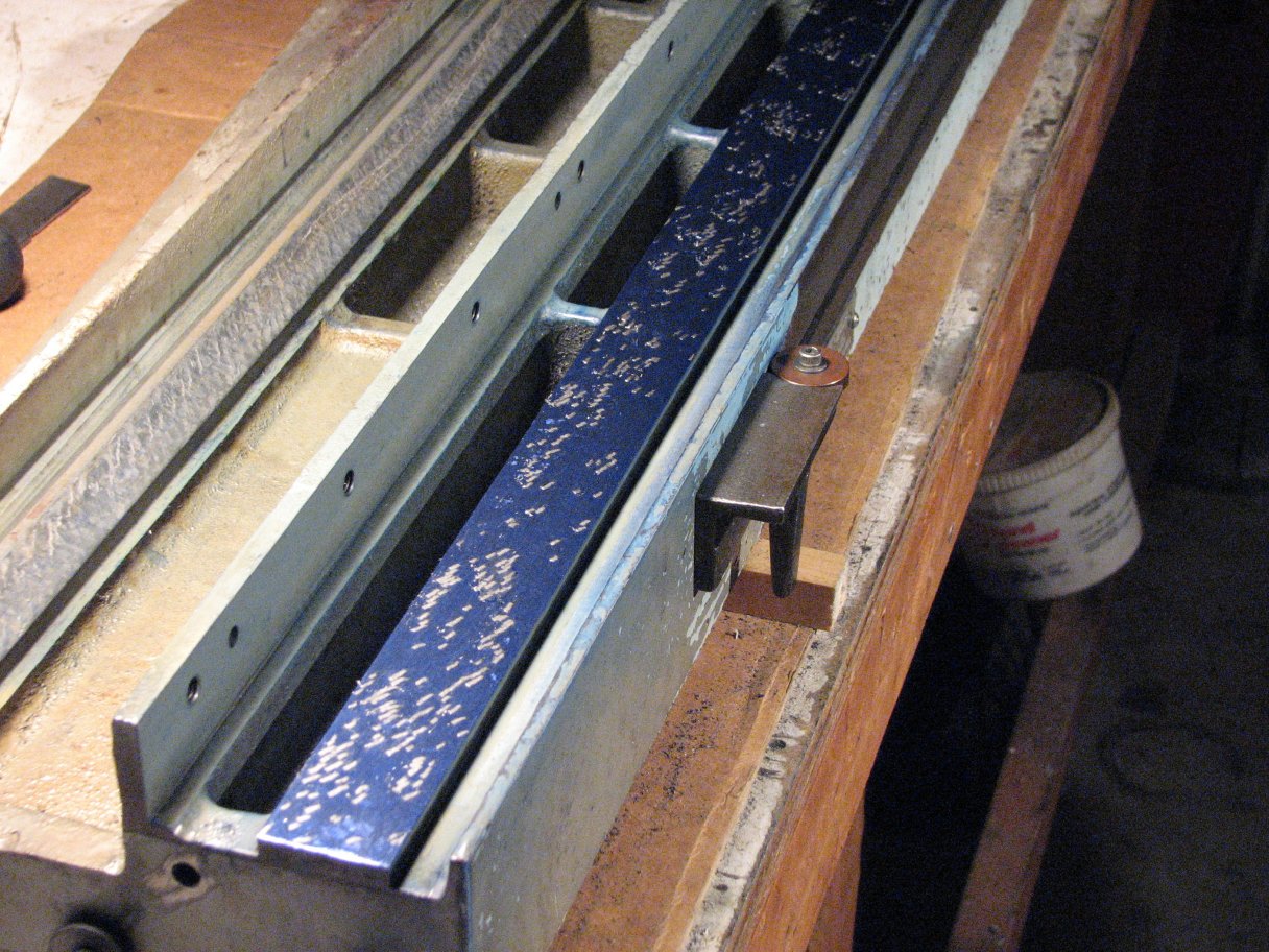
| These shots are the prints taken after changing from spotting with blue on the straight edge to reverse spotting with blue on the ways. | |
I was outbid on a nice
looking 90° inverted V scraping template on Ebay tonight. It
was rather short at 20", but would have been nice for doing lathe
saddles. I really liked that it was hollow and ribbed to keep the
weight down and the rigidity up. I did win a matched pair of
36"cast iron straightedges a couple weeks back that are in pretty nice
shape. They will need a bit of scraping to clean up a couple
nicks and burrs, but when they're finished I will have a nice large set
of straight edges for scraping that will also serve as parallels for
machine setup. I have found that generally I prefer to spot from
a granite template. This is mostly because of the way that
granite hold sand transfers the Prussian blue, but also because there
is less chance of a fleck of swarf doing damage to granite than to cast
iron. However, the down-side of granite is the weight. The
granite masters I own and have seen weigh more than a cast iron master
of the same length.
 |
 |
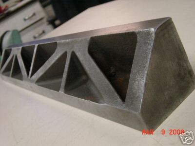
| Lost
Auction: A nicely made V template. |
The
flat way is done and I'm starting the inverted V. |
Week of March 23, 2008
I was able to spend a little more time scraping this week and have
finally gotten the flat way of the table finished to about 15 points
per square inch. Before I get started on scraping the inverted V
ways of the table, I want to scrape one of the cast iron straight edges
I purchased. I have 2 of these 36" two-sided straightedges.
Both have one scraped and one ground side. The ground faces are
pretty flat, but have lots of nicks and scratches that I have taken a
stone to. The scraped surfaces also have nicks and scratches, but
these sides will need to be rescraped.The reason I purchased the cast
iron straight edges in addition to the granite one is that the outboard
side of the inverted V doesn't have much room between it and the lip
that surrounds the bottom of the table. Because of this lip, the
granite straight edge won't fit in the small area. The 3' cast
iron straight edges are shaped like an "I" beam as seen from the
end view. The width of the finished surface (scraped or ground)
is about 1½" and the column of the"I" is only an inch. The
thinner "I" section will allow it to fit past the lip on the table so I
can spot the outboard side of the way. I am looking forward to
scraping the straight edge. Not only is it something different to
scrape, but I am looking forward to checking the parallelism of the two
faces of the straight edge with a couple of my Metrology tools. Namely
the K&E 71-2022 autocollimator and my shop made copy of the Rahn
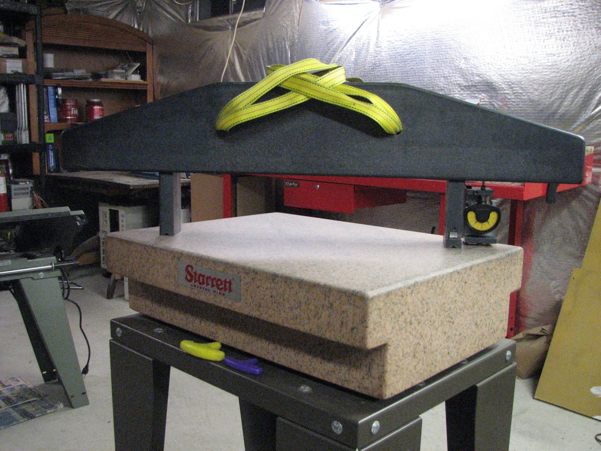
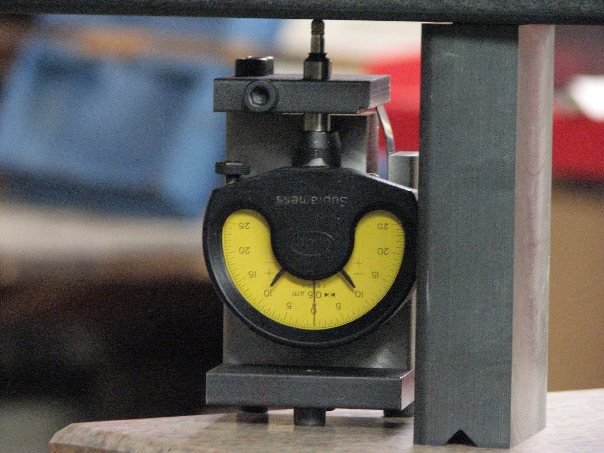
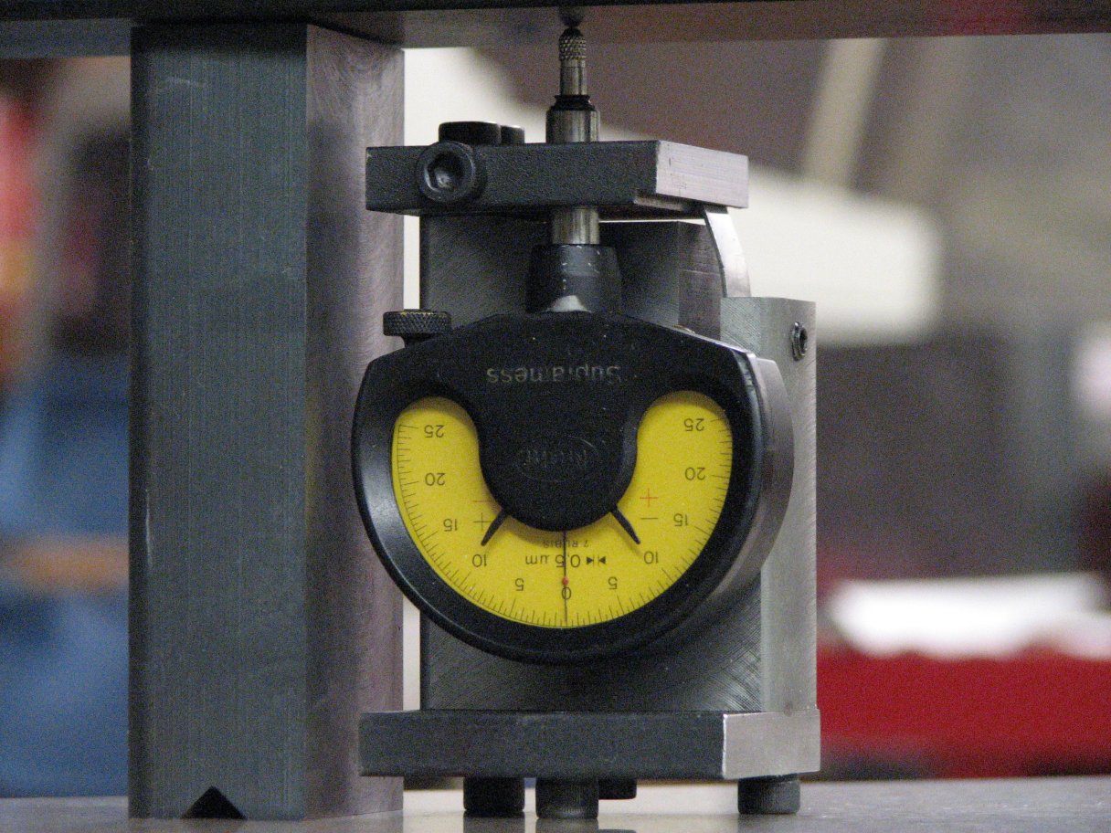
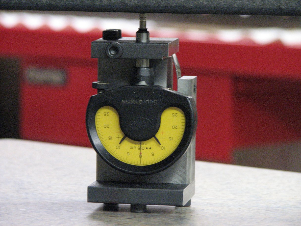
Planekator with its Mahr Supramess test indicator.
 |
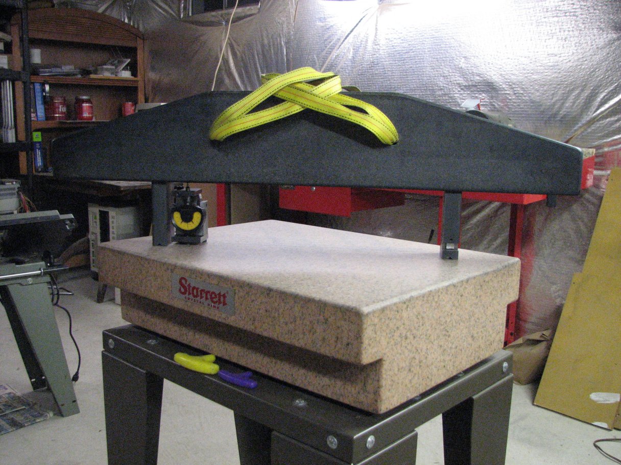 |
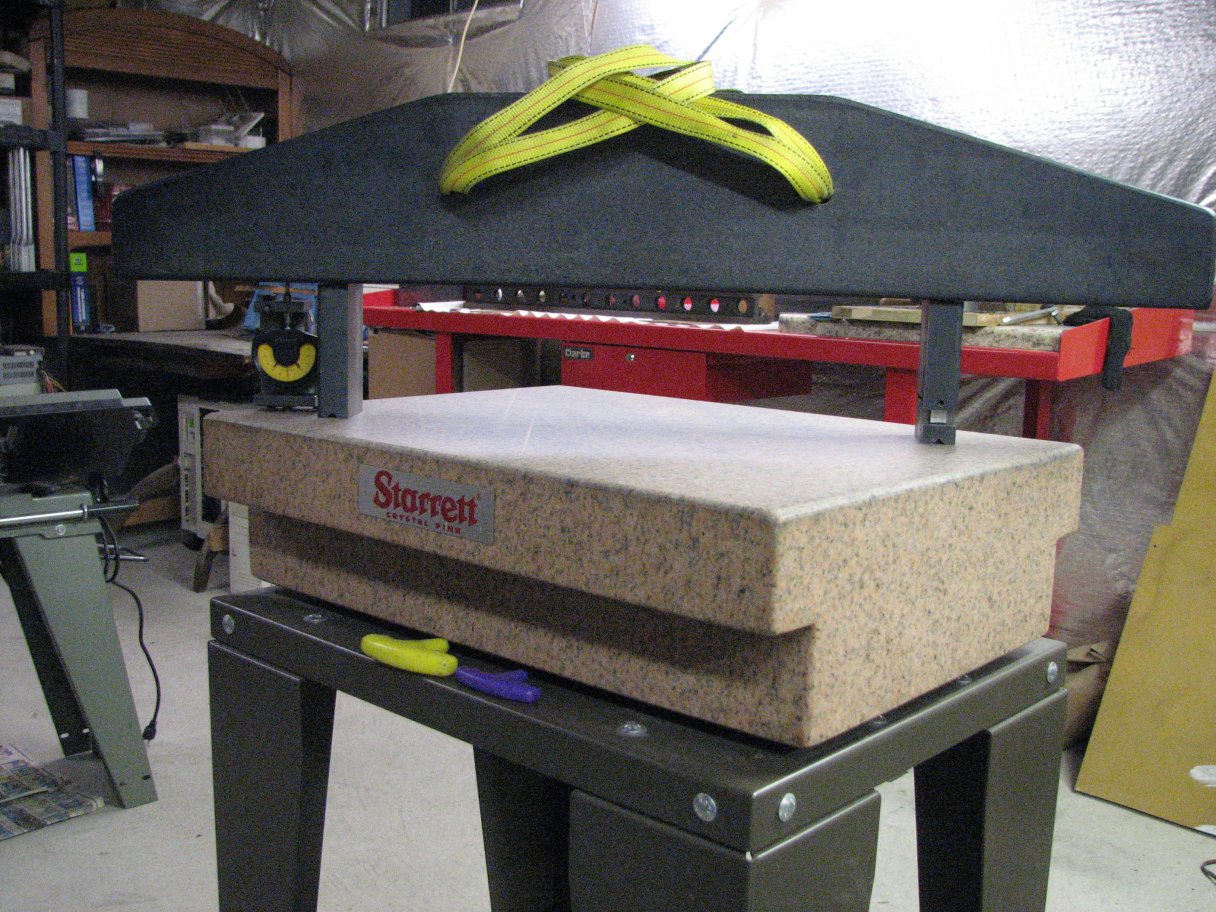
 |
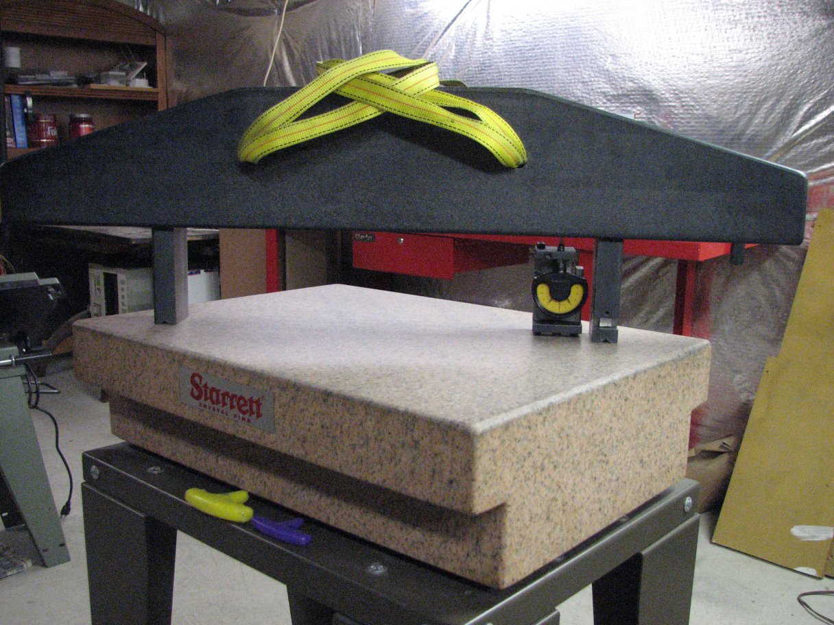 |
 |
 |
 |
 |
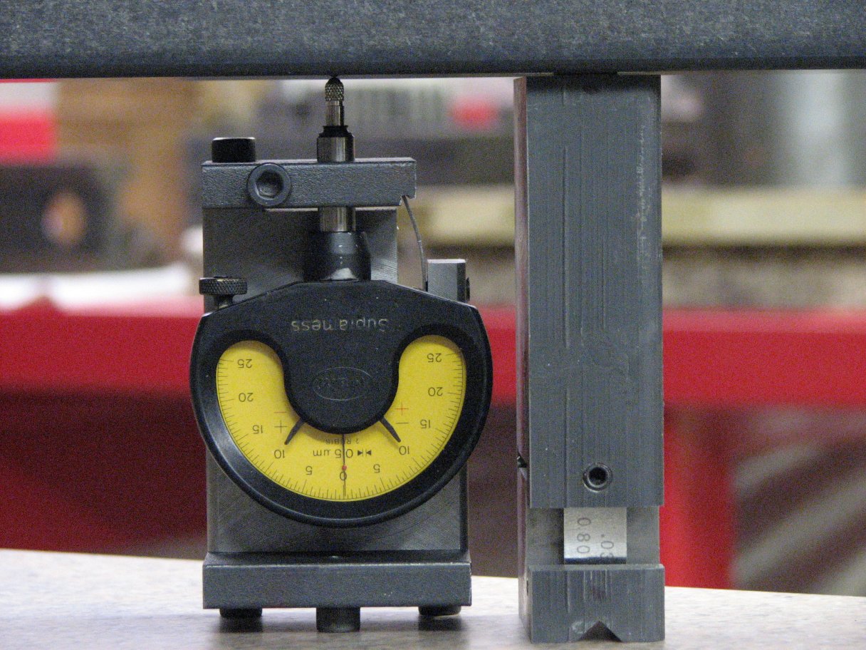 |
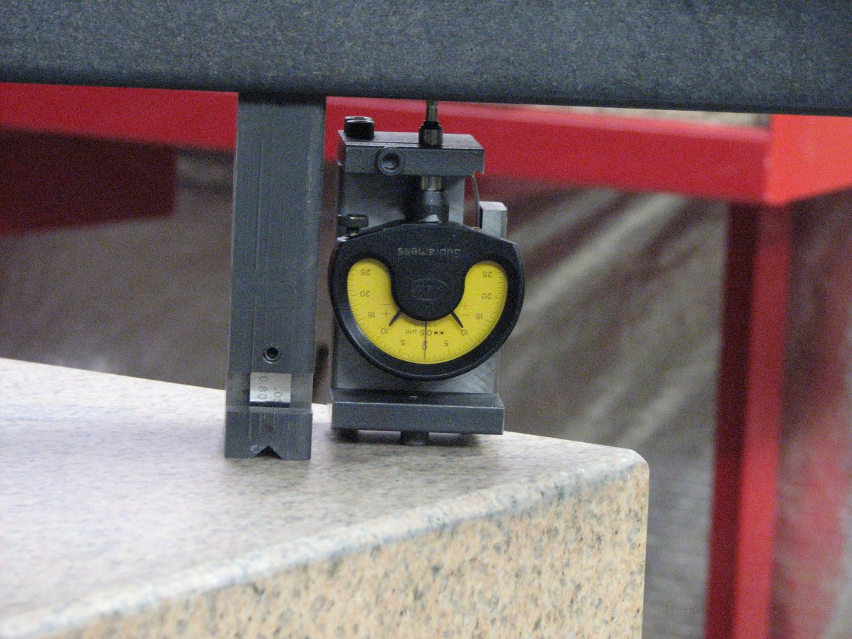 |
| My shop made copy of the Rahn Planekator allow me to read the distance between my Starrett "A" surface plate and straight edge. It shows the granite straight edge and surface plate are still pretty close to "dead flat." On the Supramess scale, each division is 0.5 µm(0.000019"). | ||||