
|
| HOME What's New
Workshop Stuff South Bend 405 Lathe Bench Grizzly G3103 Mill Bringing Home a Sheldon 12" Shaper
|

Sheldon 12"
Shaper - pg. 8
January 15, 2016
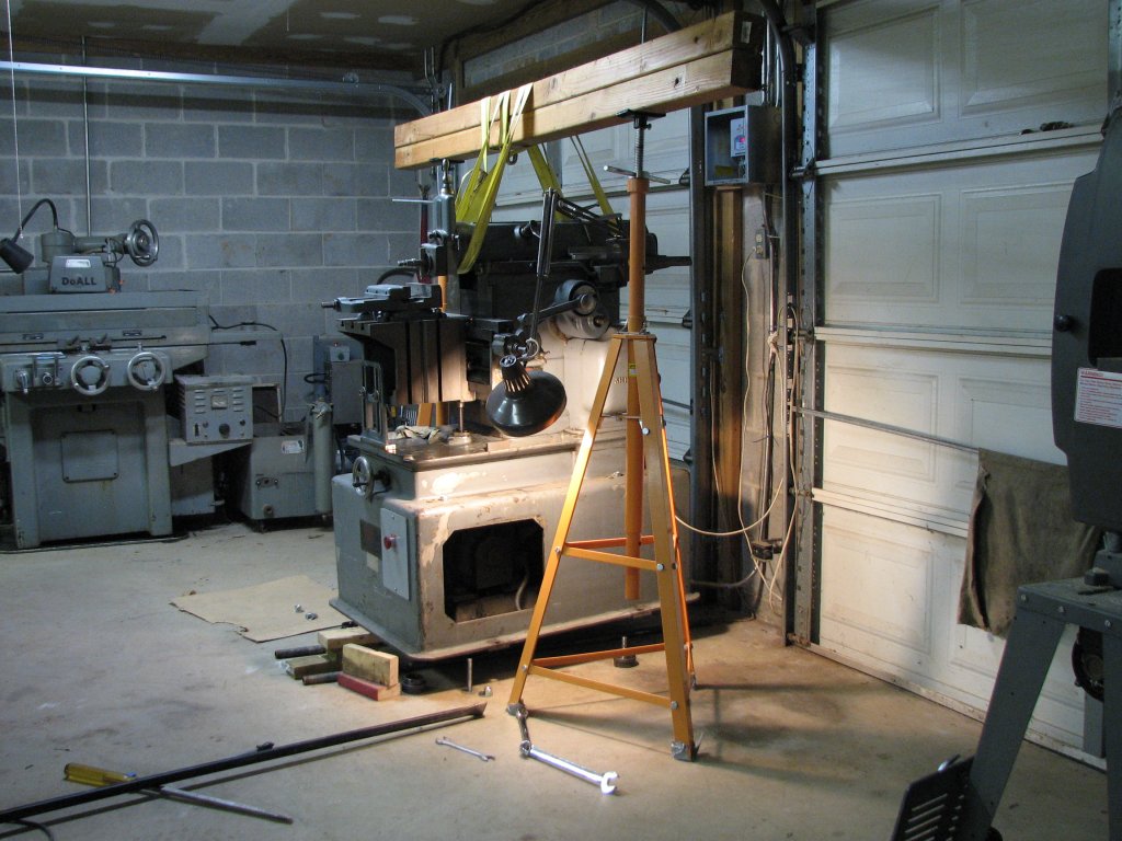
Attaching the shaper to the floor.
So far, I have
tried making a couple styles of adjuster feet to level this shaper
and prevent the machine from rocking/walking as the ram moves fore
and aft. Both were not as successful as I had hoped.
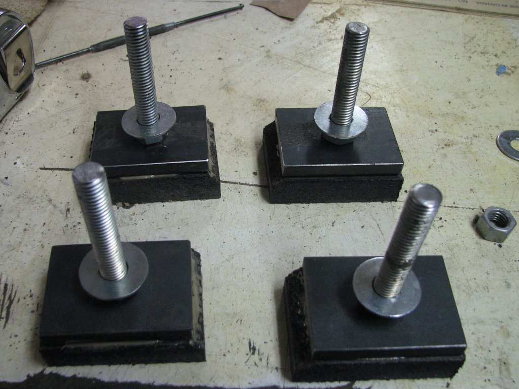
The first
attempt was making some adjuster feet with heavy rubber
pads. Unfortunately, these feet allowed the machine to rock when
the shaper was run at higher speeds and a long stroke. The rubber
was compressing too much under the force of the ram's movement.
This also caused the level to change.
The second
attempt was to remove the rubber pads and set the 3/8" thick steel
foot pads directly on the cement floor. This reduced the rocking,
but didn't stop the machine from creeping along the concrete as
the ram cycled.
With a couple of
failures under my belt, it was now it was time to see if I could
provide a secure mount for the shaper. I would attempt to attach
the shaper to the floor in such a way as to allow me to secure the
shaper, then level, and re-level as the shaper settles in.
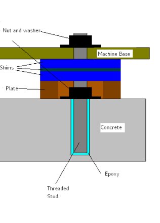
I had been reading up on the different methods of attaching machine tools to concrete and had pretty much decided on drilling holes into the concrete floor and using acrylic or epoxy to set either studs or nuts into the concrete. I had mentioned this to a friend, Dennis, who works as a plant engineer at a Newfoundland university and he helped me out with some information on the brand of adhesive he's used, A7 Redhead, and how to pre-tension the studs so that they have less chance of working loose over time. This procedure involves sinking a hole into the concrete, adding some epoxy into the hole, then installing a threaded stud. Once the adhesive has cured, a nut and washer are added to exert tension on the studs where they exit the concrete. You then add a plate with a hole large enough to encircle the nut and washer and add the shims necessary to level the machine, then use another nut and washer to attach the machine's base on top of the shims. The tightening torque for various stud sizes are included in the PDF linked above. The strength of the stud's bond with the concrete is dependent on the PSI rating of the concrete, the stud diameter, and how far you sink it into the concrete. At this point, I think I am dealing with a four inch thick concrete floor. According to the county codes when this detached garage (my shop) was built in the mid 90s, four inches of concrete laid on four inches of compacted crushed stone was the minimum thickness for a slab floor. I have no reason to think that it was poured thicker than the minimum code requirements, but will find out when I drill my first hole.
I read through the A7 Redhead PDF to familiarize myself with the product and then also read up on methods of leveling machines that were solidly attached to the floor. It would appear that using slotted shims is the standard approach and that the "best practice" was to use only three shims on any one stud. The reason for this is that there will be some air space between each shim, as well as between the plate set on the concrete and between the shim to machine base. The figures given by one manufacturer of shim kits was between 0.00025 to 0.0005" per shim. The more shims you use, the more possible air space. The more air space, the more chance the shaper will move when you tighten down the machine.Unfortunately,
the fully equipped shim kit costs more than I paid for the shaper.
Buying the shims individually would still be expensive and that
assumed that I could measure close enough to not need a lot of
extra shims. This was doubtful. Another possibility would be to
surface grind my own thicker (.25" - .50") expensive shims and buy
the less expensive thinner ones. I need the thicker shims due to
the slope of the concrete where I chose to put the shaper. The
floor has about a half inch slope between the rear right height
and the left front height. I know from experience that leveling a
machine with threaded adjusting feet is a slow process that needs
to be repeated as the machine settles in or as the seasons change.
Having to jack up each corner to insert shims would be slower
still, so I considered other ways to make the leveling
adjustments. I came up with an idea to make screw adjusters that
would surround the pre-tensioned studs. As an added bonus, this
would get rid of some of the possible air space between multiple
shims. I think this approach looks promising and I will machine
some up to see how well they work out.
 |
 |
| Attaching
the machine base to the concrete per the information I
have read. |
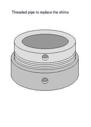
Design
for replacing the plate and shims in the previous
drawing.. |
As a proof of
concept, I made up an adjuster from 2" cast iron plumbing pipe.
Inexpensive and large enough to surround the thick washer that
will sit on the concrete.The threads are 11-1/2 TPI and tapered,
so I chucked them up in the lathe and re-cut the threads to remove
some of the taper so that I had about 1/2" of adjustment range
with good thread contact. It was a bit time consuming to pick up
the existing threads with the threading bit, but the first
adjuster turned out well enough to make the other three. I got all
eight pieces re-threaded in a couple evening's work. I then
drilled four 1/4" holes in each of the top threaded pieces to
allow me to turn the top adjuster with a pin spanner while using
an adjustable wrench on the bottom. All of the adjusters were then
put on the surface grinder to grind the top and bottom surfaces
parallel. It took a while to position each of the adjusters so
that the bores/threads were square with the grinder's table.
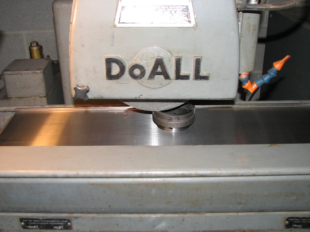 |
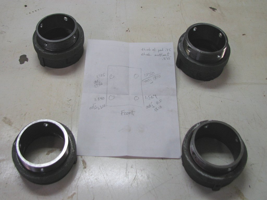 |
| Grinding the adjusters to be parallel on the top and bottom surfaces. | The four adjusters are done. The adjusters are shown the way the will sit on the concrete. |
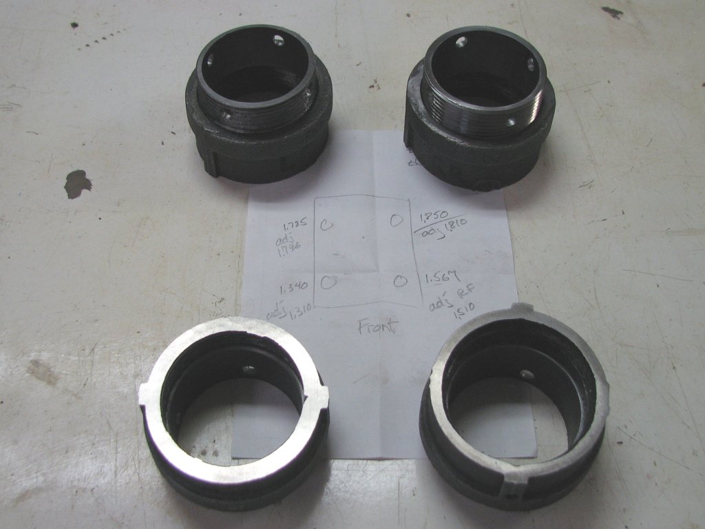
All four of the
adjusters needed to be different heights. There is a difference of
about 0.5" between the tallest and shortest. With the tallest
adjuster at around 1.8", they're a little taller than I would
like, but I needed enough height to be able to fit the pin spanner
and the one inch thick adjustable wrench to make the adjustments.
I had measured the gap between each of the existing adjusters of
the leveled shaper and the floor and cut and ground the new "ring"
adjusters as close as I could get them to those measurements.
Hopefully the shaper will be close to level without having to
start the leveling process from scratch.
 |
 |
| The two
adjusters in the front are shown bottom side up. |
Once
each hole was drilled, it needed to be cleaned of concrete
dust. |
I lifted the
shaper with my improvised gantry and set it on pipes so that I
could roll it from side to side as I drilled the holes in the
concrete. By being able to roll it from side to side, I wouldn't
have to disconnect the wiring conduit. Once I had centered the
shaper where I wanted it, I punched marks in the concrete for my
holes. I started with a 1/4" bit in the hammer drill and drilled
down about 4". I pushed the bit a little farther and broke through
the slab at about 4.5". I followed this up with a 3/4" bit.
Now that I had confirmed that the slab was about 4" thick, the
remainder of the holes would be drilled just shy of that depth. I
made a short plug up from some 3/4" OD pipe with a wood dowel
fitted inside and sunk it into the first hole to stop the adhesive
from running out of the bottom of the hole I broke through on. The
masonry bits tend to wander a little, so once I had the two holes
on the right side drilled, I rolled the shaper over the holes and
inserted my 5/8" studs through the holes in the shaper's base,
then rechecked the punch marks on the left side. I rolled the
machine to the right and drilled the two remaining holes. After
checking that all four studs fit the machine base and the holes
without any of the studs being tilted, I was ready to clean the
holes and apply the adhesive.
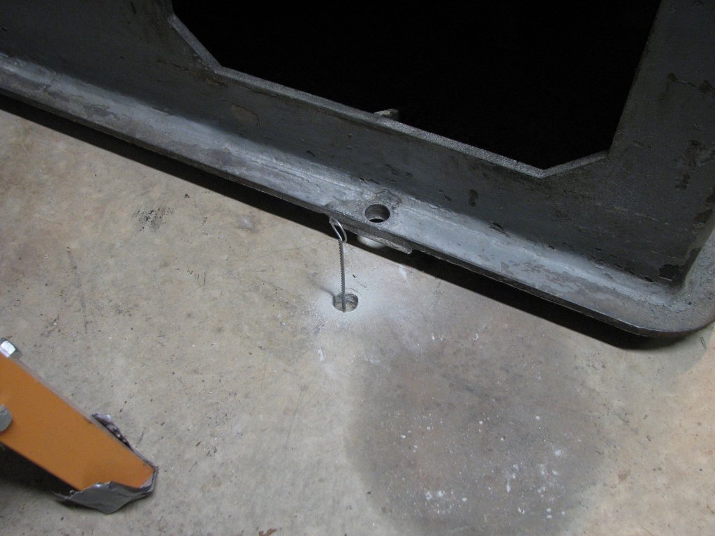
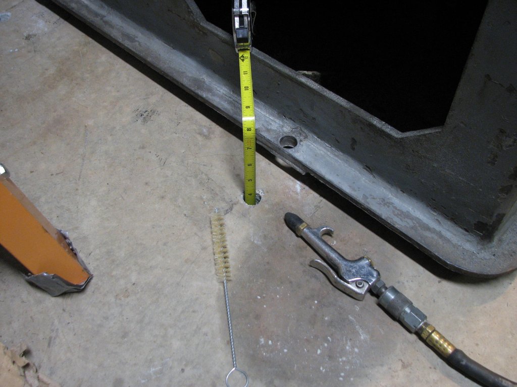 |
 |
| A staged photo showing the hole depth and the cleaning tools. | The ring adjusters are set outboard of each hole and the studs are test fit. |
When I had
looked for the A7 Redhead adhesive, I found that Home Depot
allegedly carried it. When I went to purchase it, I was told that
it was only carried in their larger stores. I was told that they
had something similar. Sika Anchorfix-2. The tubes didn't have
much info other than the curing time at each temperature range, so
while I was in the store, I found the Anchorfix-2
specification PDF online and compared it with the A7 specs.
Very close to the same specifications for pull out strength. I'd
give it a try.
The instructions
state that the holes need to be cleaned of any loose material. I
used a round brush and compressed air to clean the holes until I
saw no more dust when pumping the brush up and down.
I moved the
shaper back over the holes and placed my adjusters just outboard
of of their respective final positions. Each adjuster was set to
it's final estimated height plus 0.375" to compensate for the 3/8"
raised pad surrounding each hole on the shaper's base. I wanted to
make sure that the 5/8" studs would align with the 3/4" holes in
the shaper's base once the adhesive cured. There wasn't enough
room to use a square to check for the studs being perpendicular,
so I used some 3/4" OD / 5/8" ID bushings to center each stud in
the machine's base. It wouldn't be good if I couldn't lift the
machine off the studs once the adhesive set up.
 |
 |
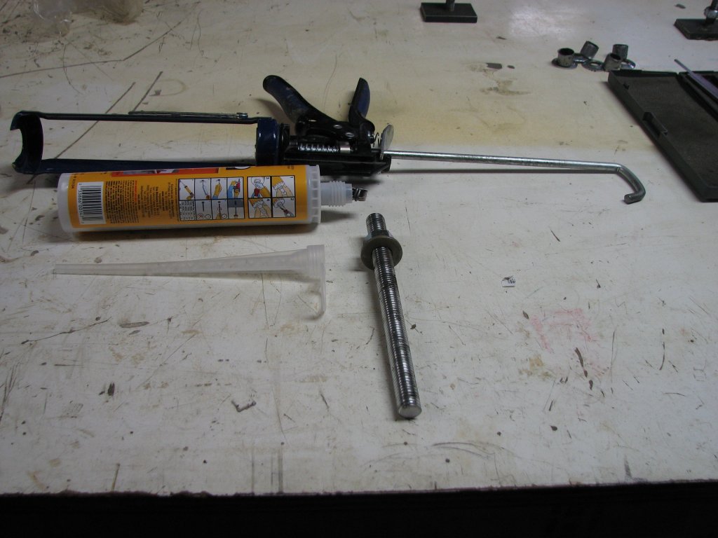
| The setup for attaching the shaper - Sika Anchorfix-2 adhesive, a fairly stout caulk gun, and one of the four 8" long, 5/8" - 11 tpi studs. | Fill the 4" hole with the adhesive to a little more than 3/4 filled. Screw in the stud and wipe the excess off the concrete. The nut supports the stud. |
With the shaper
aligned with the holes, it was time to set the studs. I removed
each stud and filled the hole a little more than 3/4 full of the
adhesive. I then threaded the stud into the adhesive until it
reached the bottom of the hole. I placed my flanged bushing
between the stud and shaper's base, then added a washer and nut. I
tightened the nuts just enough to make sure that they remained
vertical. I rechecked all of the studs a couple times to make sure
that they hadn't shifted position and left the adhesive to cure.
We've had a warm week for January (high 50s to mid 60s°F) and the
temperature of the slab was about 35°F. The curing time for the
adhesive was said to be about 3 hours with the concrete being
+32°F to +41°F. Below 32°F, the curing time is 24 hours. I'd let
it set up for 24 hours just to be on the safe side.
 |
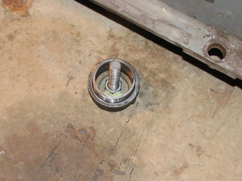 |
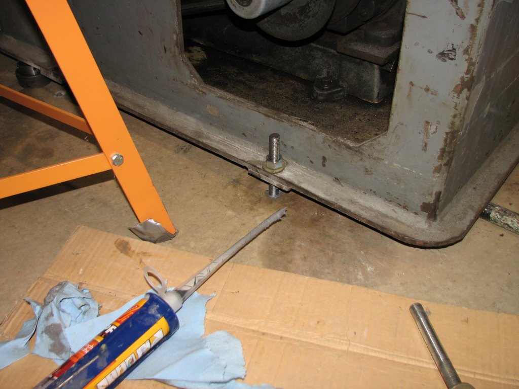
| After curing, the first stud's nut (right rear) is pre-tensioned to about 80 foot-pounds and the adjuster ring is set in place. Only three more to go. | Closer view. A 3/16" thick washer with nut surrounded by the ring adjuster. |
The next
evening, I set up to install the nuts and washer to pre-tension
the studs. Since I hadn't unhooked the wiring and conduit, this
required me to lift the shaper a couple of times to get access to
each of the studs. I made sure that each washer sat flat on the
concrete, then torqued the nuts down to 80 foot pounds. This is
the specified upper limit for a 5/8" stud in a 3/4" diameter hole
and is said to give a tension bond strength of over 3000 pounds
for a 4" hole depth. After setting the height of each adjuster per
the measurements I had taken previously, each adjuster was
installed over the stud. We'll see how close the measurements I
took of the leveled shaper turn out to be.
 |
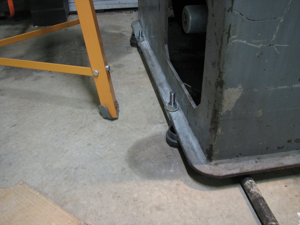
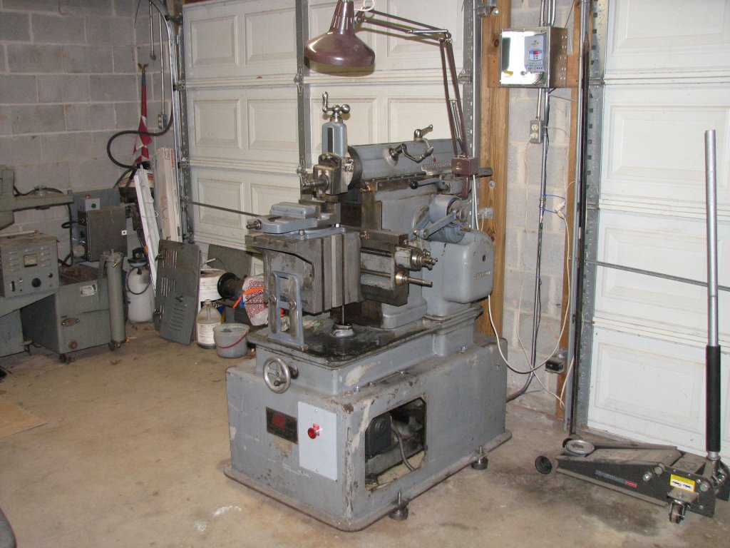 |
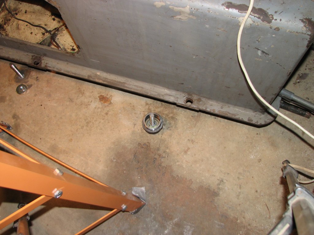
| Lifting the shaper so I can get the nut, washer, and adjuster on to the front right stud. | The shaper is now resting on the four ring adjusters. The next step is to level the machine. |
With the shaper
now sitting on the four adjusters, I was ready to level the
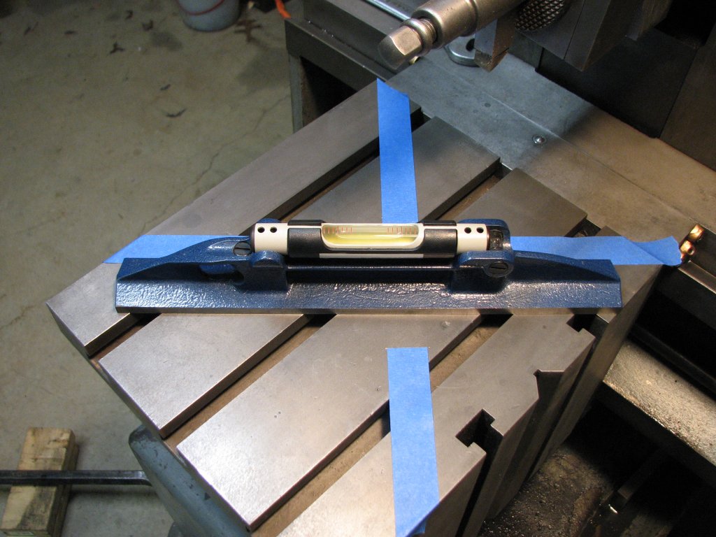
machine. I laid out some tape lines on the table to form an X with
90° angles, then cut some tape away to allow the levels to contact
the table. I would level the table in three steps. First with my
Moore and Wright 12" level that has a resolution of 0.0035"/10",
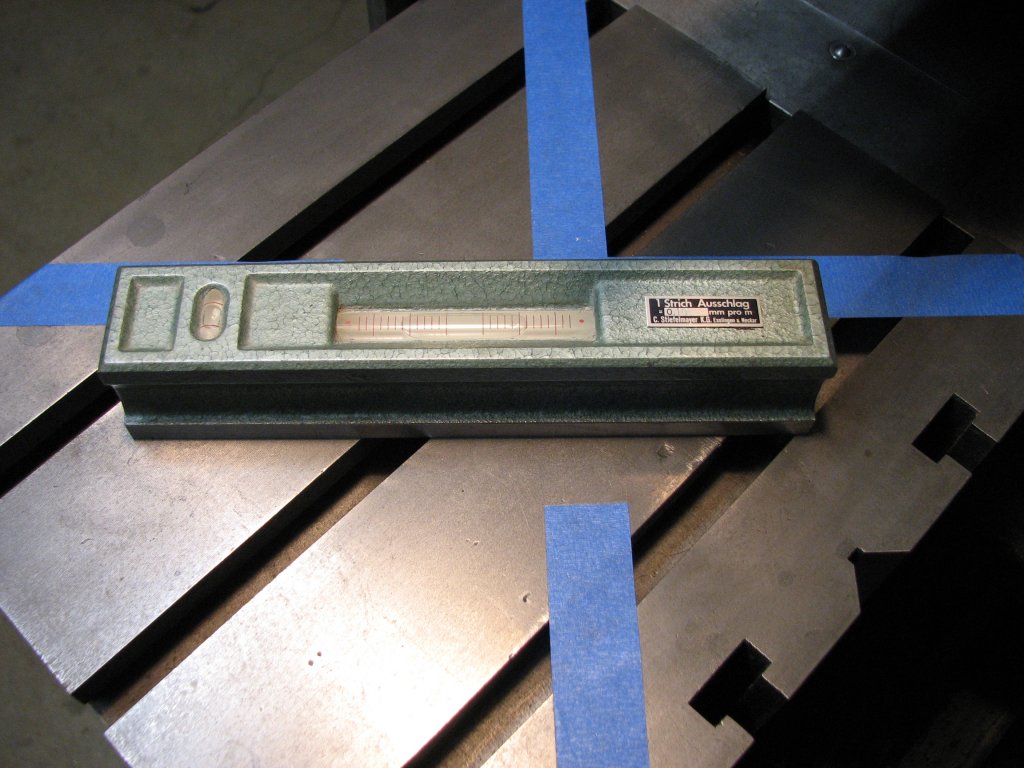
then my new to me Stiefelmayer 8" level that was a Christmas
present from my friend Dennis. Its resolution is 0.001"/10". I
like measuring tools a lot and I am quite pleased to have another
quality level. Thanks Dennis.
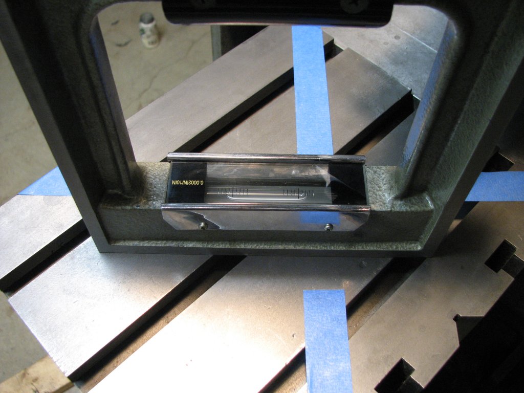
Last, I would
make the final adjustments with my import frame (box) level that
has a resolution of 0.0002"/10". I could have skipped using the
Stiefelmayer, but wanted to play with my new toy. I had previously
checked it against itself and my import level on the surface plate
and it's within a quarter increment of reading true. Somewhat
puzzlingly, it does not appear to have a vial adjusting screw - or
at least, I haven't found it yet. I will need to do some reading
to see how the level is calibrated.
 |
 |
| Using
the 12" Moore and Wright 0.0035" per 10" engineer's
level to get close. |
Opposite angle. We're within a quarter of an increment of level. |
Using the Moore and Wright, I found that one diagonal was set about as perfectly as the level can read. The other was out by one division. I guess I did a pretty good job of measuring. I reset the ring adjusters to make the correction, then reversed the level to cancel out any error and rechecked the readings. The level was centered on both diagonals.
 |
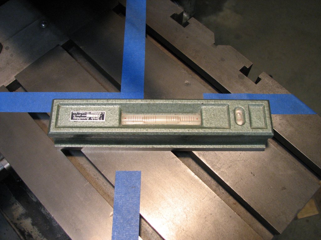 |
| Checking
with the
8" Stiefelmayer
|
Interestingly, this more accurate level was spot on in agreeing with the Moore and Wright. |
The Stiefelmayer
level's bubble was spot on for both diagonals even though the
resolution is three times higher. This surprised me a bit and I
reversed the level a couple times to recheck, but the bubble
centered each time.
 |
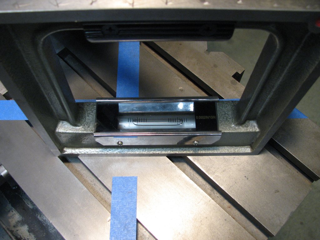 |
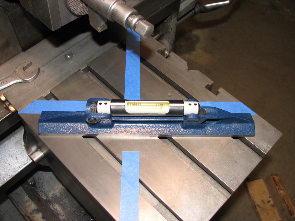
| The
last adjustments were made with my import frame (box)
level. 0.0002"/10". This diagonal showed about 1 increment
(0.0002") out. |
While I don't think that the machine will stay leveled to this precision, it is repeatable tonight with the temperature in the shop at 50°F. |
The import level
showed two increments out on one diagonal and one out on the
other. I made the adjustments to bring it as close as I could get
it to level and installed the top nuts and washers that would hold
the machine to the floor. I now needed to tighten the nuts to
about 15% less than the 80 foot pounds of the pre-tensioned studs.
As I guessed it would, the level now changed by a couple
thousandths. I tightened the nuts incrementally in an X pattern.
Each additional 10 foot pounds I tightened one nut brought the
shaper out of level, then back into almost level when I tightened
the opposite nut. When I reached 70 foot pounds for all four nuts,
the machine was out of level in both directions by about a
thousandth. I messed around with the adjusters for another couple
hours and got it within one division in either plane with the full
70 foot pounds on all nuts. The shaper was now level to 0.0002"
per 10" for the time being. I called it quits for the night.
I highly doubt
that the shaper will stay leveled to this precision. I am pretty
sure that in the past six years that the shaper has not been
secured to the floor. The pads on the flange that the adjusters
rest against are only 3/4" thick and the rest of the flange is
only 3/8" thick. It's not what I would call that sturdy of a base.
Since the previous owner didn't have the shaper on adjustable
feet, I assume that there had been unequal pressure on the four
pads when it sat on his concrete floor. I am guessing that this
might have imparted a bit of twist to the shaper's base. Couple
that with the fact that my shop is only heated when I am in it and
the concrete's rate of expansion is different than that of the
cast iron
shaper base, I figure that it's going to move around some as it
gets settled in. How much, I don't know, but I will be interested
to find out. After re-leveling a few times as the base settles in
on the adjusters, I hope I can keep the shaper's table close to
level for those critical setups that happen every once in a while.
 |
 |
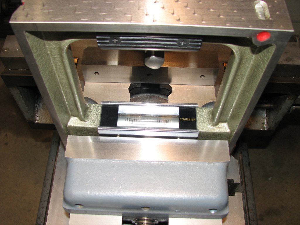
| Checking
the level of the vise jaws two days later. The shaper has
stayed level so far. It's reading a half increment high on
the left - 0.0001"/10". |
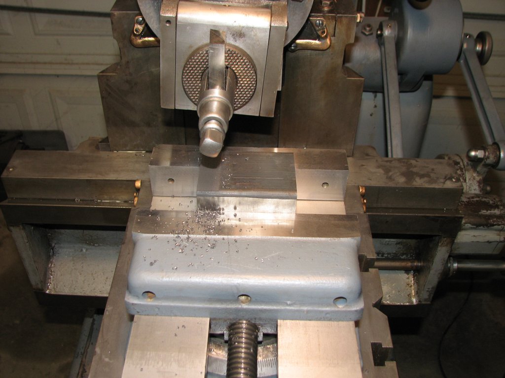
Starting the next project by squaring up some cast iron Durabar. This will become the quick change tool post holder for a rotary broach. |
It took me two
days to get back out to the shop. I checked the table for being
level and it hadn't changed. I reinstalled the shaper vise and
checked the vise rails for level. It was one tenth high on the
left side. I'm pleased with that. We'll see how well the shaper
stays level once I run it for a while.
Speaking of
running the shaper, bolting it to the floor has made a big
difference in the way the shaper runs. It's more quiet and
operates more smoothly now. I didn't realize how many of the
noises that I previously heard were simply due to the shaper
rocking against the concrete floor. Of course I now wanted to put
the shaper to work and make some chips. I spent a little time
squaring up some Durabar for the next project and tried cranking
up the stroke speed. I am now able to run the shaper at full
speed. There is no more rocking or shaking and the clapper doesn't
bounce as much as it did before the shaper was secured to the
floor. This alone is worth the time spent on securing the machine.
I am finally to the point that I feel comfortable that I can use
the shaper to make some projects.
The next project
is to make a new crank handle for the shaper. The current handle
had been broken and welded back together. While it works, I'd like
one that both works and looks good. The handle uses a 1/2" square
hole to attach to the four square shafts it fits on. Cutting the
square hole is a perfect project for a rotary broach. Since I
don't own one, I will try my hand at making one. I'd like to make
one that will attach to the lathe's quick change tool post, so I
will need a tool holder that can hold a couple bearings. Making
the broach tool holder will require me to cut some dovetails. This
will be a good way to get some practice using the shaper. I am
looking forward to spending some time working with the machine.
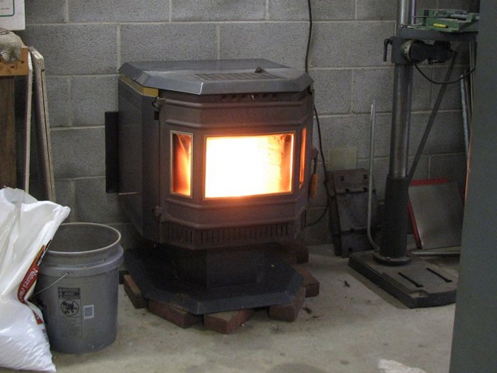 |
| I finally have a better heat source in the shop. The water vapor and rust producing propane heater was replaced with a pellet stove. It works well. |
| Shaper 1 |
Shaper 2 |
Shaper 3 |
Shaper 4 |
Shaper 5 |
Shaper 6 |
Shaper 7 |
Shaper 8 |
Shaper
9 |
© Fager January 15, 2016