
|
| HOME What's New
Workshop Stuff South Bend 405 Lathe Bench Grizzly G3103 Mill Bringing Home a
Sheldon 12" Shaper
|

Sheldon 12"
Shaper - pg. 9
March 15, 2016
New Crank Handle
With the shaper
attached to the floor, I started the last shaper project for a
while. I wanted to make a new crank handle for the shaper. The
original crank was damaged at some point and cobbled back
together. The crank attaches to the shaper with 1/2" square hole
cut through a 1.3" length of bar stock which serves as the drive
for the crank. I will need to make a new square drive, arm, and a
teardrop shaped handle.
 |
 |
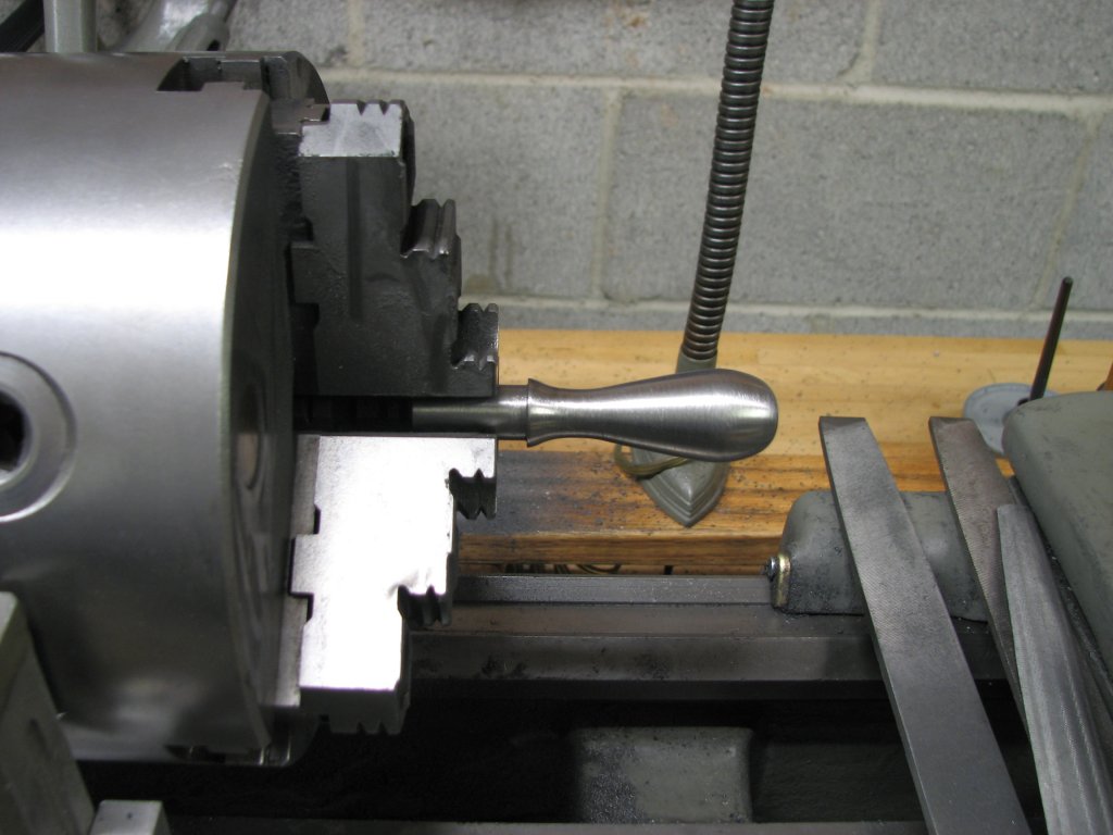
| The
teardrop handle has been roughed out by turning the major
diameters, then filed to shape. |
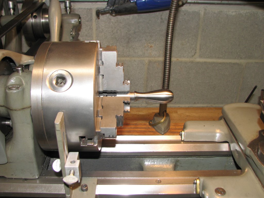
The
handle has been smoothed and polished and the lathe has
been cleaned up a bit. |
My current crank
handle is pretty crude and it doesn't feel comfortable in my hand.
I hoped to come up with a better shape for the new teardrop shaped
handle. I took some pictures of the handle on the shaper's speed
control. I also took some pictures of the handles on my grinder
and lathe. I worked on these pictures in a photo editor until I
had a rough idea of what shape I was after. I settled on a major
diameter of 0.9" for the widest portion, 0.4375" for the waist,
and the end that meets the crank arm would be turned to 0.625".
The shaft to attach the handle to the crank arm would be 0.5". I
considered making the teardrop handle able to spin, but decided
against it. I turned a rough shape on the lathe to just over the
diameters mentioned, then got out a selection of files and spent
the rest of my limited evening shop time filing the handle's
shape. This process was a lot like turning a shape on a wood lathe
- all free-hand filing until the handle looked like what I had
envisioned. Once I had the shape I was after, I used 120 grit
sanding cloth to get rid of the file marks. I then used 400, then
600 silicon carbide paper wetted with WD40 to polish the crank. I
am pleased with the outcome.
 |
 |
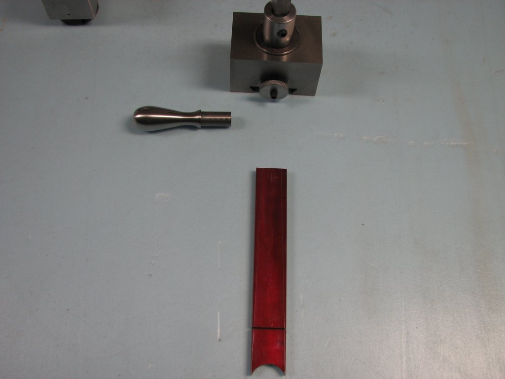
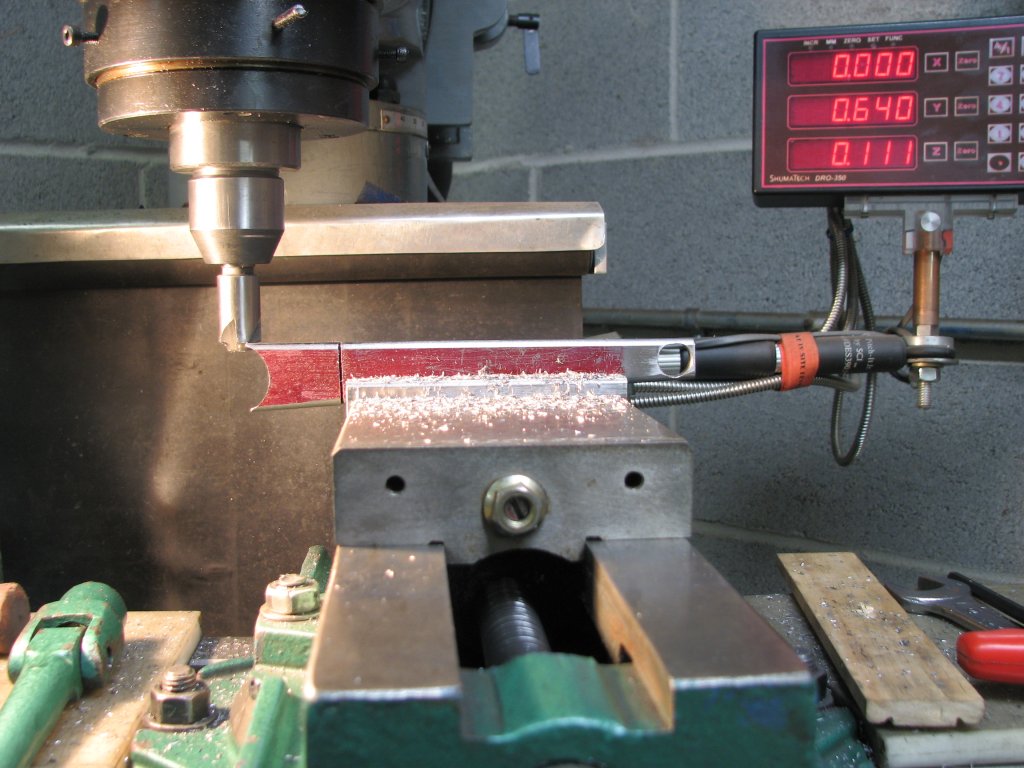
| Two
crank handle parts. The kerf on the red arm will help make
a tight bend. There's another kerf on the opposite side
for the second bend. |
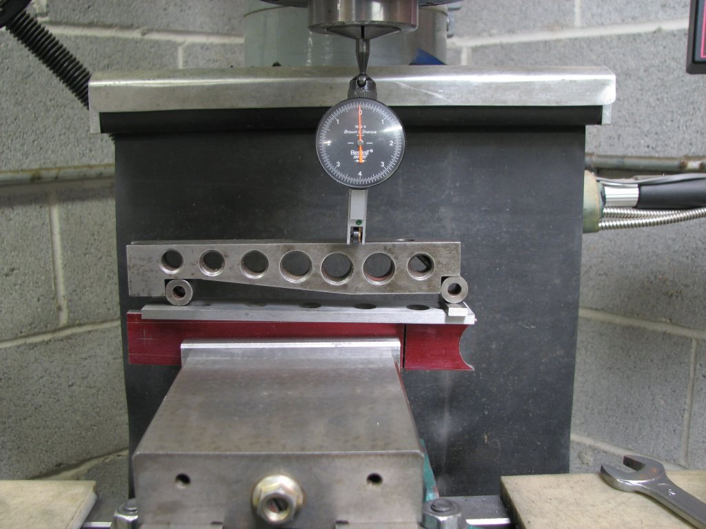
Since
the sine bar wouldn't fit under the part, I placed it on
top and set the work to the proper angle. I then realized
I hadn't drilled the hole. |
For the crank arm I decided on using 1/4" thick 1018 steel. I wanted the width of the arm to taper from the 1" diameter square-holed cylinder (driver) to the 5/8" bottom portion of the teardrop handle. I also wanted the edges of the arm to be rounded. The last consideration was that to clear any obstructions when turning the crank, the arm needed to be angled around 10°. To get nice tight bends on the angled portion of the arm, I cut kerfs about an inch from each end. I cut the kerfs with my horizontal band saw which leaves a slot of about 0.050". I opened the kerf up to a wedge shape of about 0.125" with a thin file, which will give me the proper angle on each of the two bends.
I laid out
scribe marks and milled the 1" diameter half moon on the big end
of the flat stock. To mill the angle from the 1" radiused end to
the 5/8" end, I wanted to use a sine bar to position the flat
stock in the mill vise for the angled cuts. Unfortunately, neither
my 4" or 6" milling vises had enough jaw height to fit both the
sine bar and flat stock. I ended up clamping the flat stock in the
4" vise and setting the sine bar on top of it. I used a 1/4" thick
parallel to support the sine bar and used a 0.148" gauge block on
top of the crank arm to define the angle. I set up a DTI in a
collet and adjusted the flat stock until I could traverse the sine
bar with no movement of the DTI needle. I was then ready to mill
the angle and round the edges with a round over bit. Or so I
thought. I had to laugh at myself as I had set up to mill the
angles before I drilled the hole that the teardrop handle would
fit into. I had to break down the setup and drill the 1/2" hole
that the teardrop handle would fit in to before I went any
further. If I had milled the angles before drilling the hole, I
wouldn't have parallel sides on the flat stock to clamp into the
vise. I'm glad I caught my error before I milled the angles.
 |
 |
| I
drilled the hole, then milled the part to the proper
angle. I'm using a 1/8" radius round over bit on the
edges. I'll do some filing to clean up the shape. |
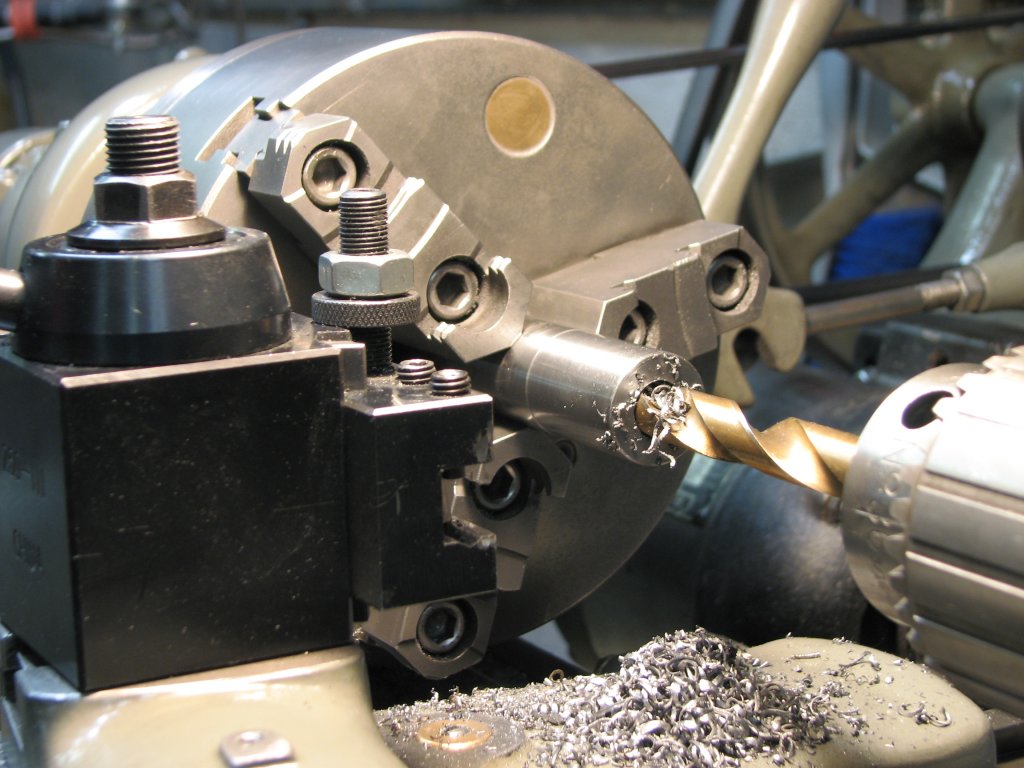
The
crank handle driver has been turned to 1" diameter and is
being drilled to 0.5" to ready it for broaching. The
length will end up at 1.3" |
The next step
was to make the cylinder that would contain the broached hole. I
turned a piece of tool steel to a 1' diameter, then incrementally
drilled it for a 1/2" hole. I then put a good sized internal
chamfer on the end that I would broach into. All that's left to do
on the driver cylinder is to broach it.
Unfortunately,
the rotary broaching didn't go so well. The shop made broach
holder and broaches work pretty well for up to 1/4" holes, but the
1/2" square that I needed to broach through 1.3" of steel put too
much stress on my little lathe. I will cut out the square hole
using the milling machine.
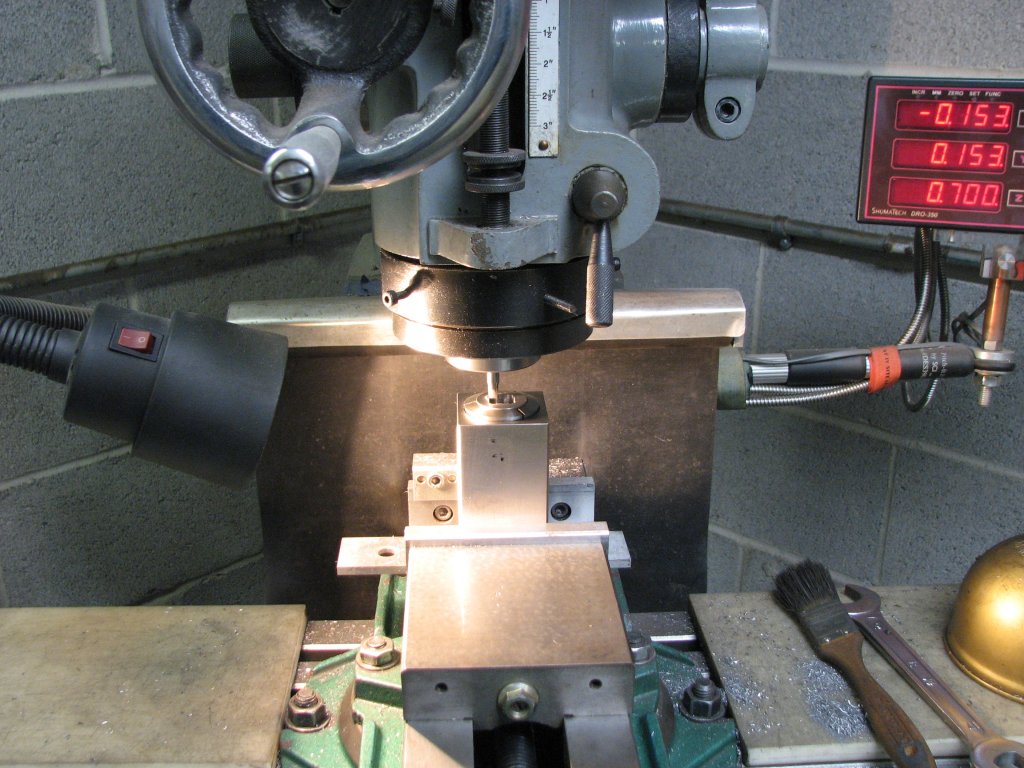
I set the crank
driver cylinder up in a square collet holder and used a 13/64" end
mill to turn the round hole into a square with rounded corners. I
sunk four holes 0.7" deep for what would be the corners of the
square, then milled out the remaining material. I then switched to
a 1/8" end mill to tighten up the corners. I again sunk four cuts
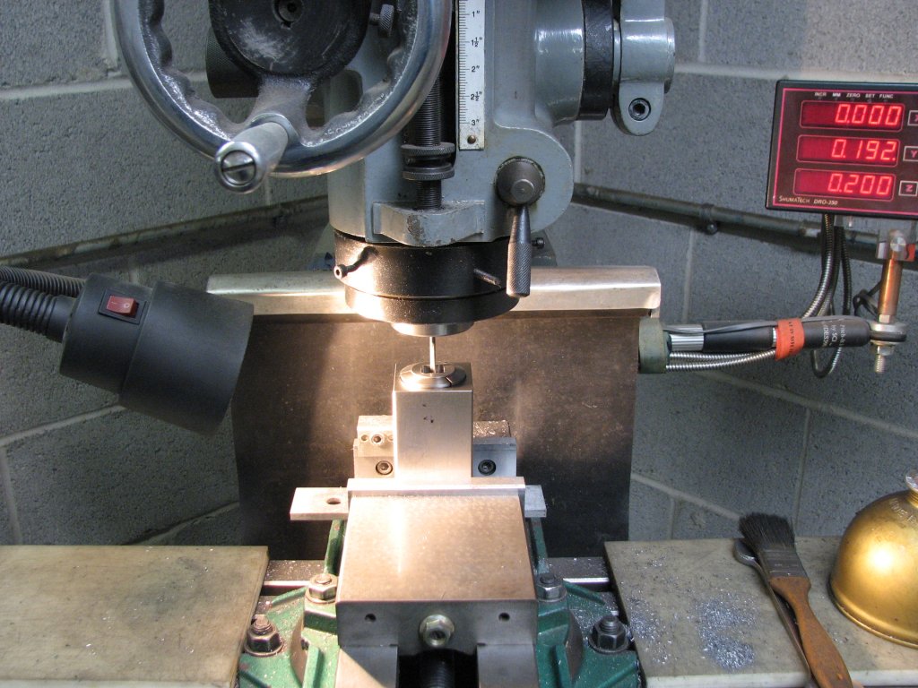
in the corners, then connected them. Since I was taking off just a
few thousandths of material, I could use a fairly heavy depth of
cut. I used 0.2" DOC for the 1/8" mill. I use the carbide 1/8" end
mills a lot, but have to be careful with them. They won't take a
lot of side force without snapping. I'm happy to say that this one
survived.
The most time
consuming part of the job was having to flip the cylinder over and
align it so I could sink the square hole on the back side and have
it match the square hole in the front. The depth of cut on the
13/64" and 1/8" end mills is only 3/4" and I had 1.3" to cut
through. To get the square hole lined up for the reverse side
cuts, I used a long stylus on my DTI and did the measuring and
setup on the surface plate. The square holder for the 1" 5C collet
made the job easier than trying to get the cylinder lined up and
cut using a V block.
 |
 |
|
Sinking the 13/64" holes at what will be the first step in
milling the corners of the square. |
Joining
the 1/8" holes along the X axis with passes that are 0.2"
depth of cut. |
To bend the arm
to the proper angles, I clamped the flat stock arm in a bench vise
and used a hammer and brass drift to bend the arm and close up the
kerf. Once the angles were bent, I needed to silver braze the
kerfs to fill them in and then file off the excess silver-nickle
braze.
I had to wait a
day to do the silver soldering to assemble the crank handle. My
oxy-acetylene brazing rig was almost out of oxygen and the
acetylene was also getting pretty low. Prices for acetylene have
risen quite a bit from the last time I filled my tanks. This
didn't surprise me too much as it's been at least five years since
the last time I had the tanks filled. They're only 80 cubic foot
tanks, but they don't get a lot of use.
For silver
soldering flux, I use either white FB3A or black FB3C paste flux.
The black flux has boron included and is able to withstand higher
heat for some carbide to steel applications. I used the white flux
for this job. I find that cutting a small piece of the silver
solder and laying it on the joint, then heating the metals (not
the solder) until the solder starts to flow helps to ensure that I
have enough heat to braze the joint. I then add more silver solder
as necessary to fill the joint. You don't need much solder as the
parts should be placed in very close contact to each other. I use
a lot of flux but try to be careful to keep the flux only where I
need the silver to flow. The solder seems to follow the flux to
where ever it is, so you need to be careful when applying your
flux. Too much solder will make for more filing and obviously
wastes the expensive silver solder. As you can see in the picture
below left, I got a little too much solder on the left side of the
arm to driver joint. I didn't do a good enough job of wiping up
the extra flux before I started brazing.
 |
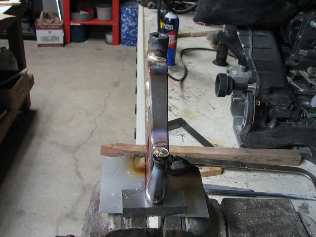 |
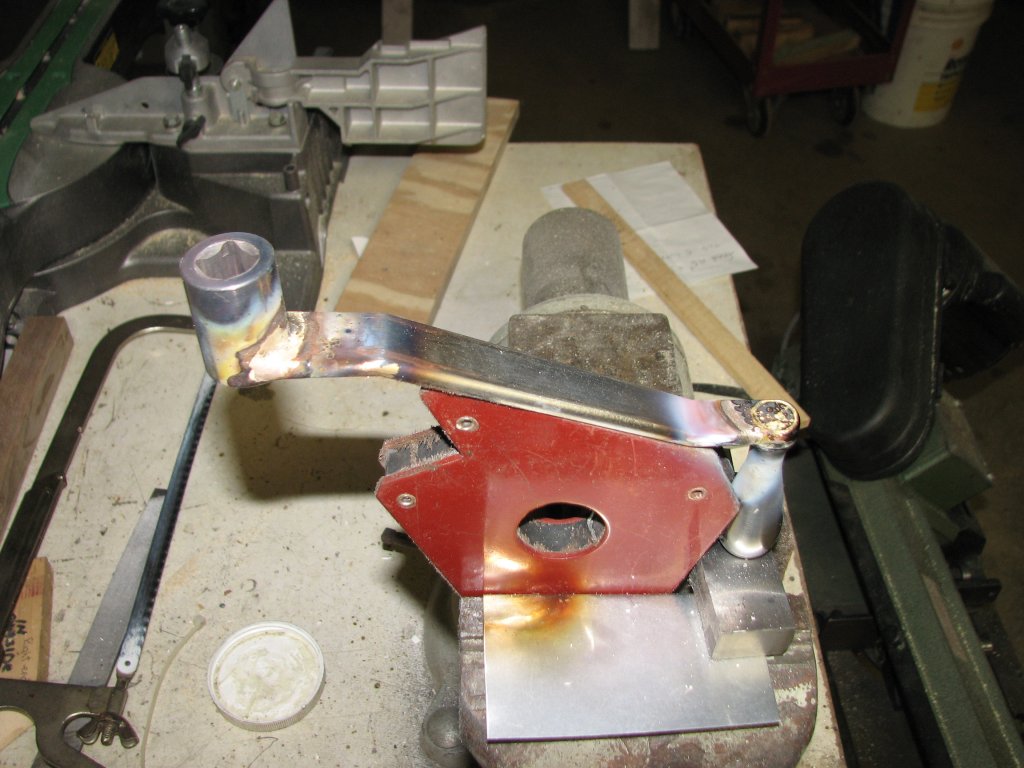
| The
cylinder is brazed on the bottom side after being already
brazed on the top. The teardrop is brazed on the bottom,
but wicks to the other side. |
I got a
little too much solder on the drive cylinder joint. This
will make for a little more filing and sanding. |
Cleaning up the
excess braze is a job that some people hate, but I tend to enjoy.
Filing is one of those jobs where once you get into a rhythm, you
can zone out for a while. Repetition and some good music makes the
time spent seem short.
I spent an hour
or two blending the brazed parts into the arm and cleaning up the
teardrop handle. Once I was happy with the way the crank looked, I
lightly sanded the surfaces with 400 grit silicon carbide paper. I
cleaned the crank with lacquer thinner and taped off the teardrop
handle. I was ready for paint. I sprayed a couple coats of primer
and called it quits for the evening.
 |
 |
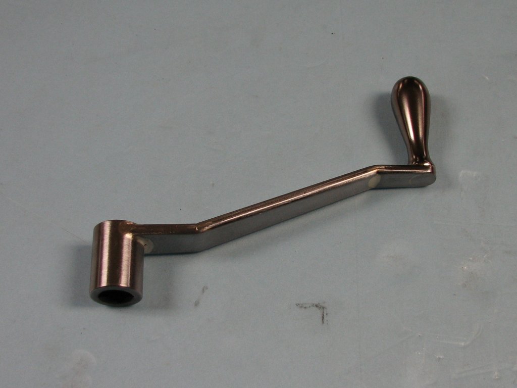
| The
filing and sanding have been completed. I'm pretty pleased
with how it looks. |
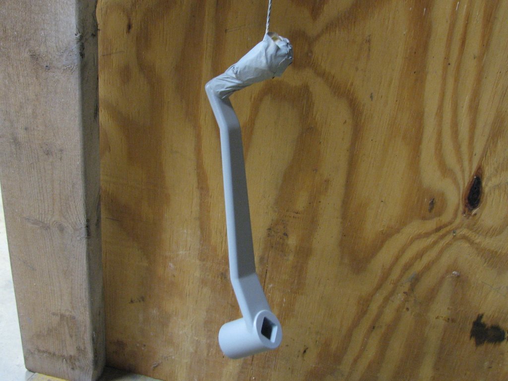
A
couple coats of primer have been sprayed. I'll add the
color coat in the next day or two. |
I sanded the
primer with 400 paper, then cleaned the surfaces and shot on the
color coat with my artist's air brush. I like the air brush for
small jobs because it is much easier to clean than my larger spray
guns. Over the next few days, I sprayed three coats. The color is
Tractor Supply machine gray enamel with about an ounce and a half
of black added to the quart of gray. I added some hardener and
thinned the small cup of the mixed paint with about 10% mineral
spirits to get it to shoot properly though the air brush. The
picture below right shows pretty close to the true color since it
was taken without the camera's flash.
 |
 |
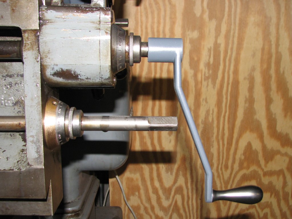
| The
crank handle clears the second shaft with a bit to spare.
The handle is a little longer than the stock handle by
design. |
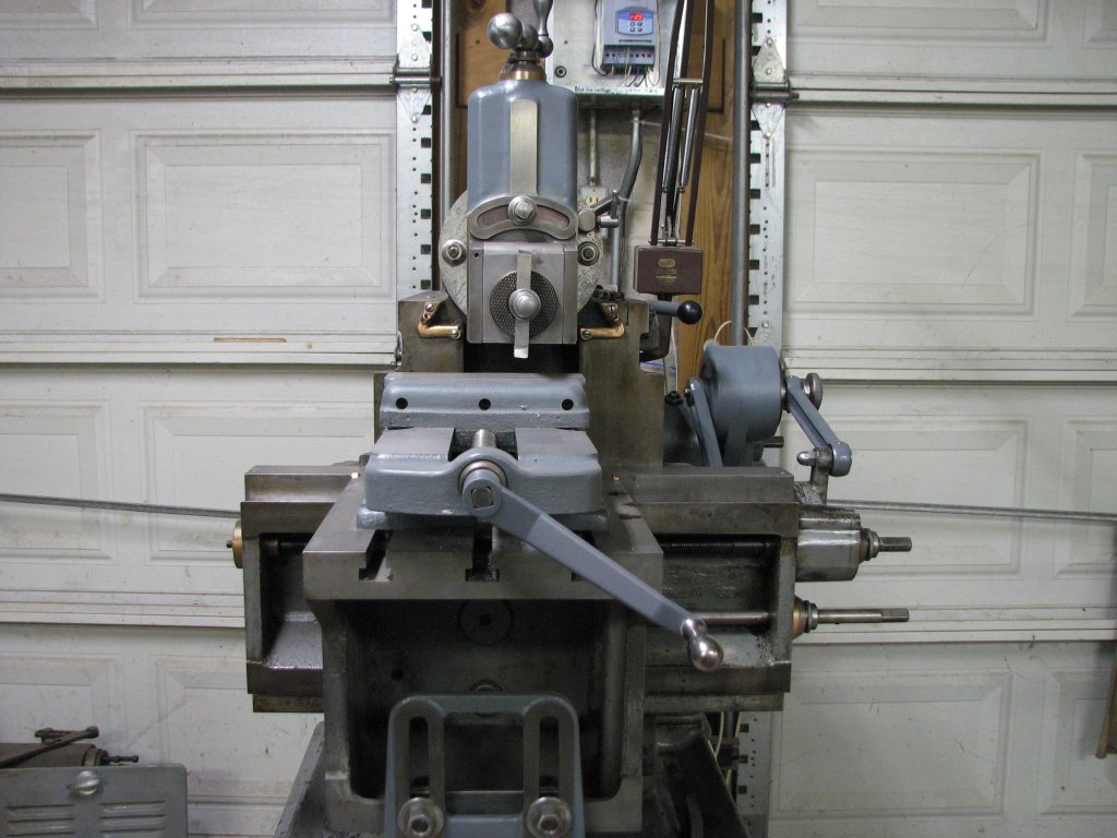
One
more view of the handle. Unlike how they show in the
picture, all of the newly painted surfaces are the same
color. |
The project
turned out pretty well. If I hadn't spent so much time building
the rotary broach, it would have been done a lot sooner. However,
the rotary broach is a neat tool and there will be other uses for
it.
While I would
prefer to have an original unmolested handle, the new handle is a
lot nicer to use than the old one and it looks a bit better.
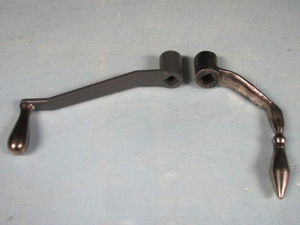 |
| The new
crank handle and the one that came with the shaper. I
think that the new handle works and looks a bit nicer. |
| Shaper 1 |
Shaper 2 |
Shaper 3 |
Shaper 4 |
Shaper 5 |
Shaper 6 |
Shaper 7 |
Shaper 8 |
Shaper 9 |
© Fager March 15, 2016