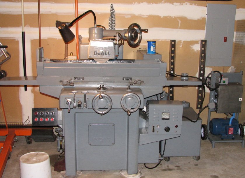
The grinder is finished. 11 months of work and I'm pretty pleased
with the outcome. The last few months have been busy ones and I
haven't had the time to spend to do much more than take some pictures
and make some notes on my progress.
June/July 2008
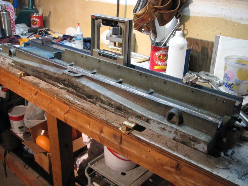
The lower saddle ways were done. The grinder had been moved to
its new home in the corner of the garage and leveled. The top saddle
ways were flat, true and square to the lower saddle ways and the column
ways. Best of all, I was getting closer to having the table ways
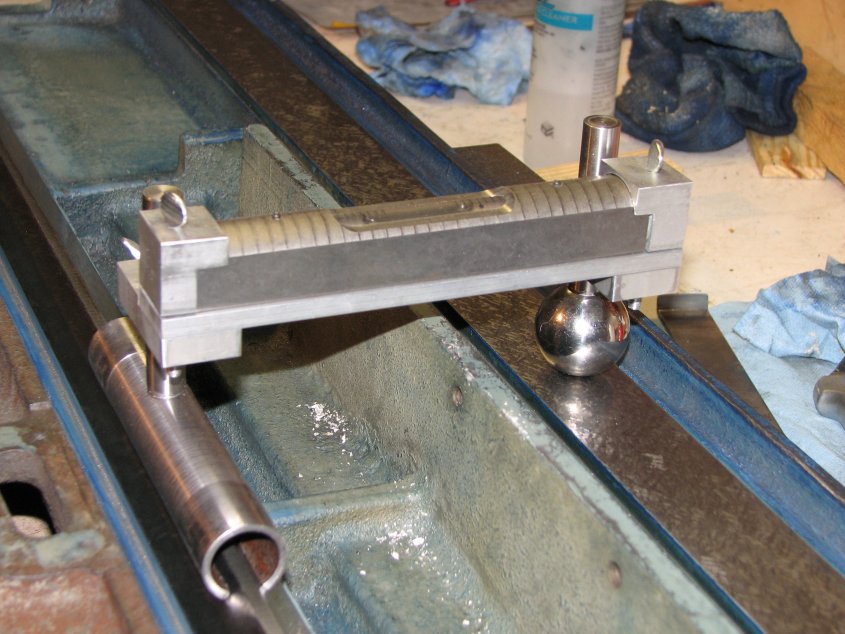
finished. One of the last checks involved using my shop made
"KingWay" type tool, which was used to ensure that the inverted Vee way
was parallel to the flat way. My tool, having only a single vial,
can only check for level in one plane, but this is not an issue if
additional levels/vials are used to make sure that the ways are level
in the length plane. To level the table, I used my box
level and a couple of vials I had made with no curvature. Without
a barrel shape or a slight bend in the vial, the sensitivity of the
bubble in the vial is greater than the 0.0002" per 10" of my box
level. Actually, they're too sensitive. Any vibration on
the garage floor would put the bubbles in motion, but as long as the
bubbles stayed somewhere near the center of the vial, I knew that the
table was pretty darn close to being level. I used the box level
to confirm this.
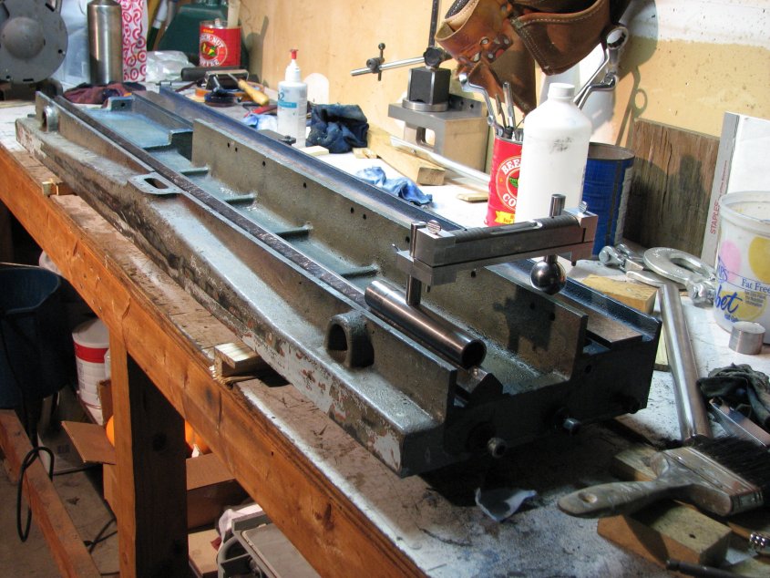
Once I had shimmed the table
level at the Airy points, the "KingWay" tool was used to check that the
inverted vee and flat ways were flat and not angled toward one end or
the other. The final step was to use my engine hoist to lift the
table and set it on the saddle to perform the final scraping in
process. This step took about two weeks of bluing the table or
saddle ways, setting the table on the saddle, lifting it off and
checking the pattern of high points, and scraping them flat. Once
I had a good patten with the table centered on the saddle, I tried
setting the table in different positions - as if the table was sliding
right or left - and made my final passes.
Another check I made was to block my 36" granite straight edge, level
and square, to the top table pad. I then used a tenths indicator
mounted on the wheel housing to check for any irregularities in
travel. Since the table pad was badly pitted and corroded, this
allowed me a true, flat surface to compare the table travel to.
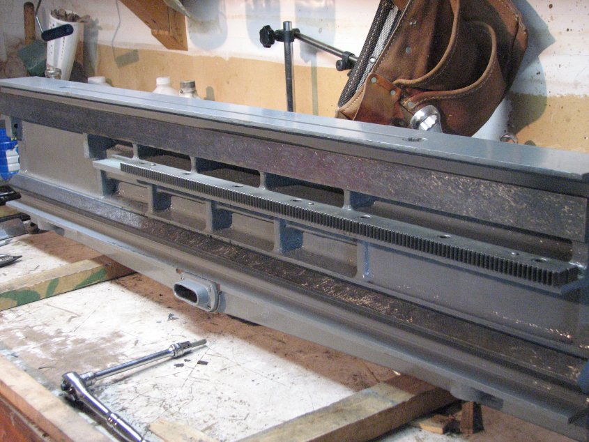
Finally satisfied with my scraping job, I repaired one damaged thread
for the coolant return fitting, painted the table, and mounted the rack
for manual table travel.
I was expecting that I would need to make some adjustments in the
mounting of the rack, as I had removed a fair amount of metal from the
ways. However, I was pleasantly surprised when after bolting down
the rack and trying it against the pinion gear on the saddle, it was
perfect. I applied Prussian blue to the teeth of the rack and ran
the rack from end to end in one direction. I got a good contact
pattern on the pressure side of the teeth and no contact on the other
side. I repeated the test for the other direction with the same
result. With the table at rest, there was a small amount of
backlash which indicated that the mesh was not too tight. This is
a little confusing to me as neither the rack or pinion appear
worn. I don't know how much backlash this machine had when new,
but it would appear that it was more than it has now. There are
dowel pins that locate the rack on the table and they fit without play,
so there is only one position for the rack to attach. I have
given this situation a fair amount of thought and the only conclusion I
can make is that the machine's designers allowed enough clearance
between the rack and pinion that it could be rescraped without having
to using up all the clearance between rack and pinion.
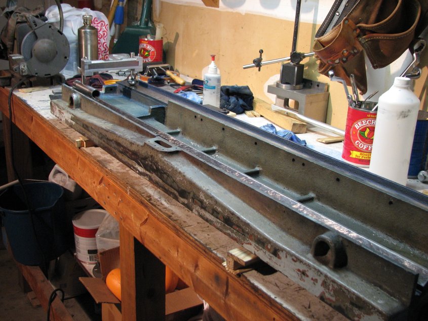
The
rack is installed and the table's been painted
With the
table on I had a couple more things to do before I would be ready to
grind the table pad and chuck. First I needed a more permanent
home for my rotary phase converter (RPC). I had been testing
different circuits of the surface grinder with the RPC parts attached
to a prototype board, while the 5 hp motor sat on the floor. The
RPC now needed a dedicated home.
September 2008
I've done quite a bit of work on DC circuits included designing some
low power amplifiers. I've also done tons of electrical work on
cars. What I had never done was to venture into the realm of
3-phase AC wiring. There are a lot of sites on the web that go
into great depth on how to convert single phase 220 household power
into something suitable for powering industrial equipment. Many
of these pages are written by folks who have a much better grasp of the
theory and electrical codes than I. With this in mind, I will
leave how I built my RPC out of this article. If you are
interested in building one for your own use, I suggest that you start
with the "sticky notes" on the Practical Machinist site "Transformers,
Phase Converters and VFD" bulletin board.
Between Ebay for a 5 hp 3-phase motor, some of the capacitors,
switches, indicator light and Grainger and my local home
improvement store for the remainder, I spent about $550 for the whole
thing. This is about $150 more than the least expensive 5 hp
units seen on Ebay, but a whole lot better quality. Also, being
on wheels allows me to move it to where it might be needed in the
future. Building it was also quite a learning experience and
after the research I did, I no longer am completely ignorant about 3
phase electricity.
The build went very quickly once I had assembled all of the parts from
the different sources. No horror stories and no problems with
balancing the phases. The one problem I did have was with the
wiring for the grinder and I had fortunately read about it, so I was
able to fix it in moments. When I wired up the plug to power the
grinder's electrical box, I made sure that the manufactured leg of the
power was not on the circuits that powered the step down transformer,
but that was about all I took into consideration. When I fired up
the hydraulic pump motor, I had no hydraulic pressure. After a
few choice words and a sinking feeling, I realized that the pump motor
was turning in the opposite direction of the arrow stamped on the
pump. Long ago, I had read that to reverse the rotation of a
3-phase motor, you may swap any two of the wires. I
reversed the two connections on the plug and moments later, I had
hydraulic pressure.
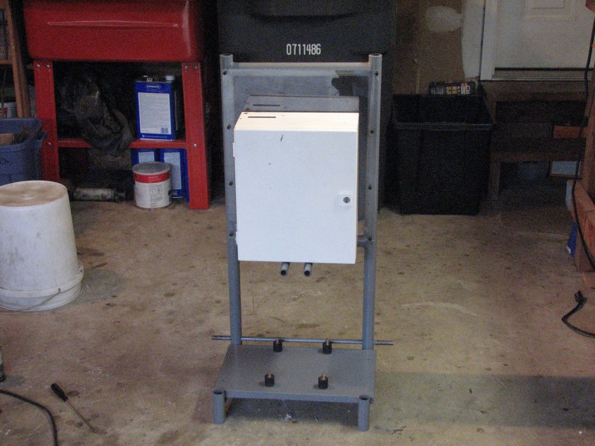
Frame for the RPC
Finished RPC at right
The fact
that I had run the pump backwards was not the only hydraulic issue I
encountered. Earlier, I had been going through the machine and
trying to find the correct hydraulic filter, which for my 1967 D624-8,
is a Purolator 572759 ( ID= 1.000/.997, OD = 1.781 max./1.735 min.,
length = 4.500/4.438,). I found a comparable filter at Filter
Mart, part number 02-0004. When I removed the bowel that holds
the filter, I found that the previous owner had installed a filter that
was about a half inch too short. A filter that is too short is
like not using a filter at all, since the oil is able to flow around,
rather than through it. I drained and cleaned the tank, flushed the system and crossed my
fingers that I wouldn't have any
troubles with it. I got lucky and it seems to perform quite well,
but it was necessary to purchase a hydraulic gauge in order to set the
pump output pressure. I also readjusted the release pressure of
the pressure relief valve. Once I
had the pressure set to specifications (300 PSI for the Continental
Hydraulics 113620-E Hyd Pump), I noticed that the pump quieted down and
the motor wasn't working as hard to spin the pump. The hydraulic
system seems
to be in pretty good shape, though I do get a little seepage from the
seals on the hydraulic cylinders.
When the hydraulics are switched on, the Bijur lubrication pump is also
powered up. Since I had already found and replaced the clogged
metering jets early in the
inspection and repair process in mid-summer, it works like a
champ. I had replaced the 3 size 0 - B2495 and 3 of the size 2 -
B2497 metering units. In the past, I have had very
little luck trying to clean Bijur metering jets, so I didn't even try
messing with these. After all of the time I have
spent scraping the ways, the last thing I want to do is to run this
machine with
little or no lubrication. While looking over the lubrication
system, I found it interesting that only the vertical
and longitudinal axes, as well as the vertical lead screw use
metering jets. The saddle in/out axis (Z ways) are lubricated by the excess
table
lubrication. The run-off from the X axis table ways
collects in depressions, then enters the vee ways from holes directly
above them. These ways do get more than enough lube and tend to
drip a bit from both the front and rear of each vee way, but it's
better to have to clean the drips than to have dry slides.
September 2008
The last thing I needed to take care of before I could give the grinder
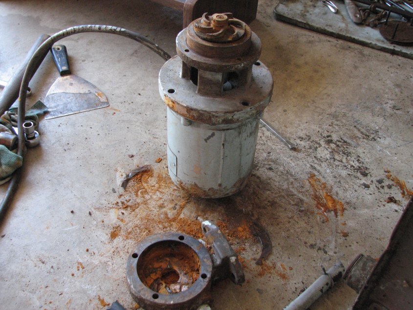
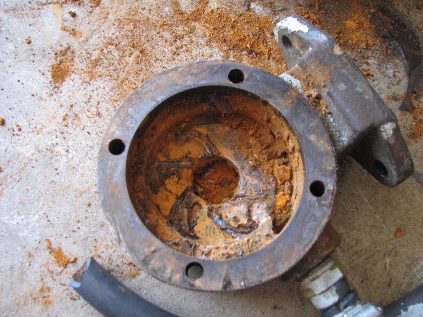
a try was to get the coolant working. I had noticed that the pump
was locked and wouldn't spin, but figured that I could repair it
without much trouble. This turned out to be correct. It
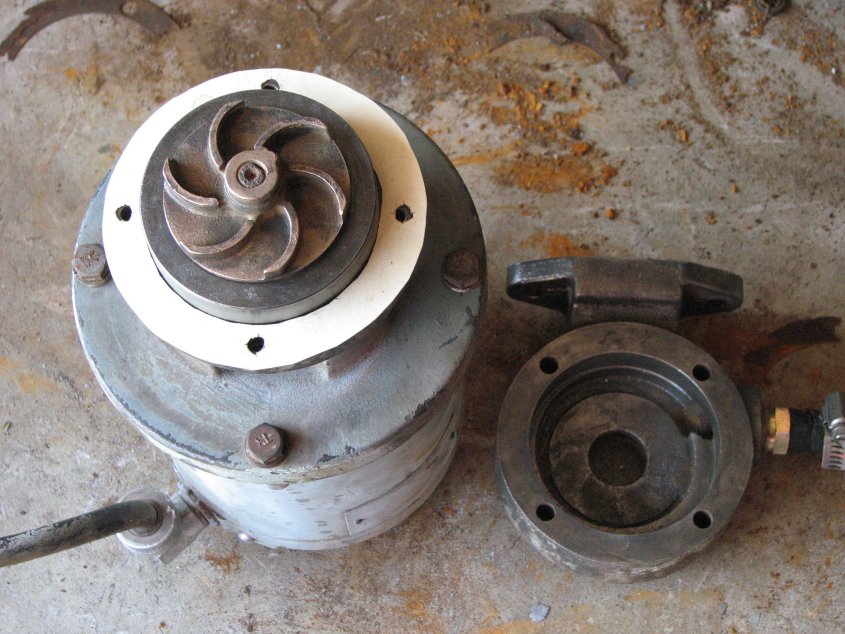
appears that the impeller just rusted to the housing. I spent a
couple afternoons stripping the tank, pump, filter, and motor down to
their basic parts. I wire-brushed the impeller and housing to
clean off the rust. I opened up the filter to find that just like
the hydraulic filter, it was too short. I wonder what the work
looked like using unfiltered coolant. The filter that was there
was a charcoal filter for drinking water purification, but since the
tank is made for a double length filter, this single length one wasn't
doing anything except maybe slowing down the flow a bit. This
grinder has the "Cool Grind" setup where the coolant is directed to
special flanges on the wheel adapter. The wheels have perforated
paper labels that allow the coolant to enter the wheel and be forced
out to the cutting edge by centrifugal force. In order not to
clog the wheels, extra filtering is added. In addition to a new
filter from McMaster - a 20" filter # 4411K65, I also added a felt bag
that
catches sediment as it enters the tank. This cuts down on the
amount of material that ends up in the tank and filter.
I brush
painted the 20 gallon holding tank with Rustoleum enamel and let it
cure for a week or so before filling the tank with a coolant/water
mixture. I have plumbed in a line-lock nozzle and a valve to
switch between the Cool Grind function and the normal flood
coolant. When I initially ran the pump, I got a little seepage
from the seal between the impeller and motor, but this sealed itself
after it had been run for a while. It is replaceable, but who
knows what pressing the impeller off would be like.
October/November 2008
With everything finished, I set out to grind the table and chuck (see this page). As I explained in that
installment, I encountered some spindle issues. The taper on
the grinder's spindle was worn from use - and probably not tightening
the adapter before starting the spindle. I was somewhat concerned
about trying to grind the spindle taper myself on my South Bend 9"
using
my shop made tool post grinder. However, I figured I'd give it a
try and if I
couldn't get the taper close enough to NO run-out, I'd find a machine
shop to grind it for me. I knew that the bearings would need to
be replaced as even if they weren't worn, I wouldn't be able to get
them out of
the housing and back in again without doing some damage to them.
I also
knew that they would be expensive. New Barden 107 matched angular
contact bearings go for over $600 a pair. I would need two
pair. Ouch!