
|

Sheldon 12"
Shaper - pg. 2
July 23, 2015
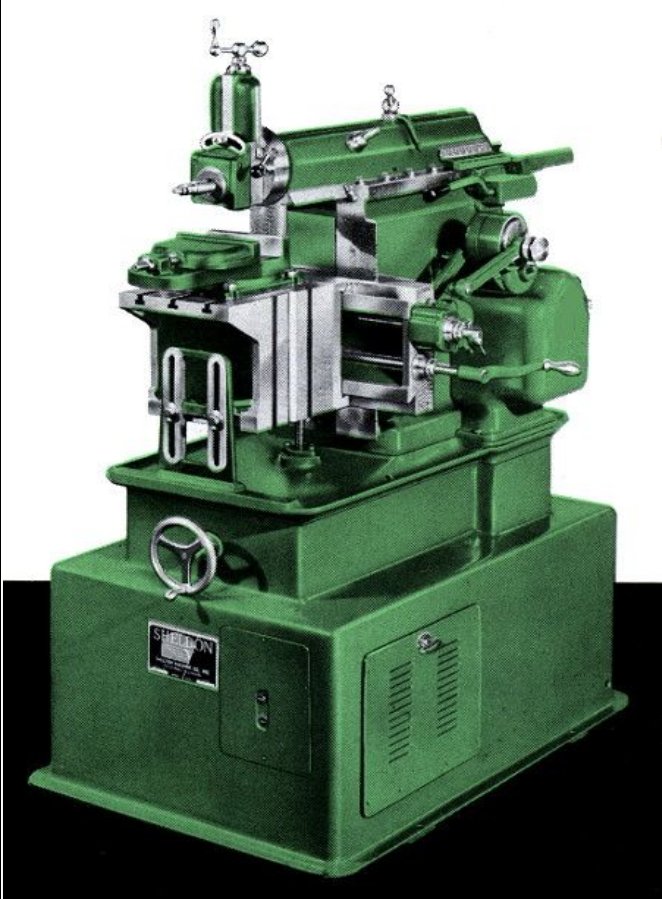 |
| An artist's rendering of the Sheldon 12" Shaper from an advertising brochure. |
 |
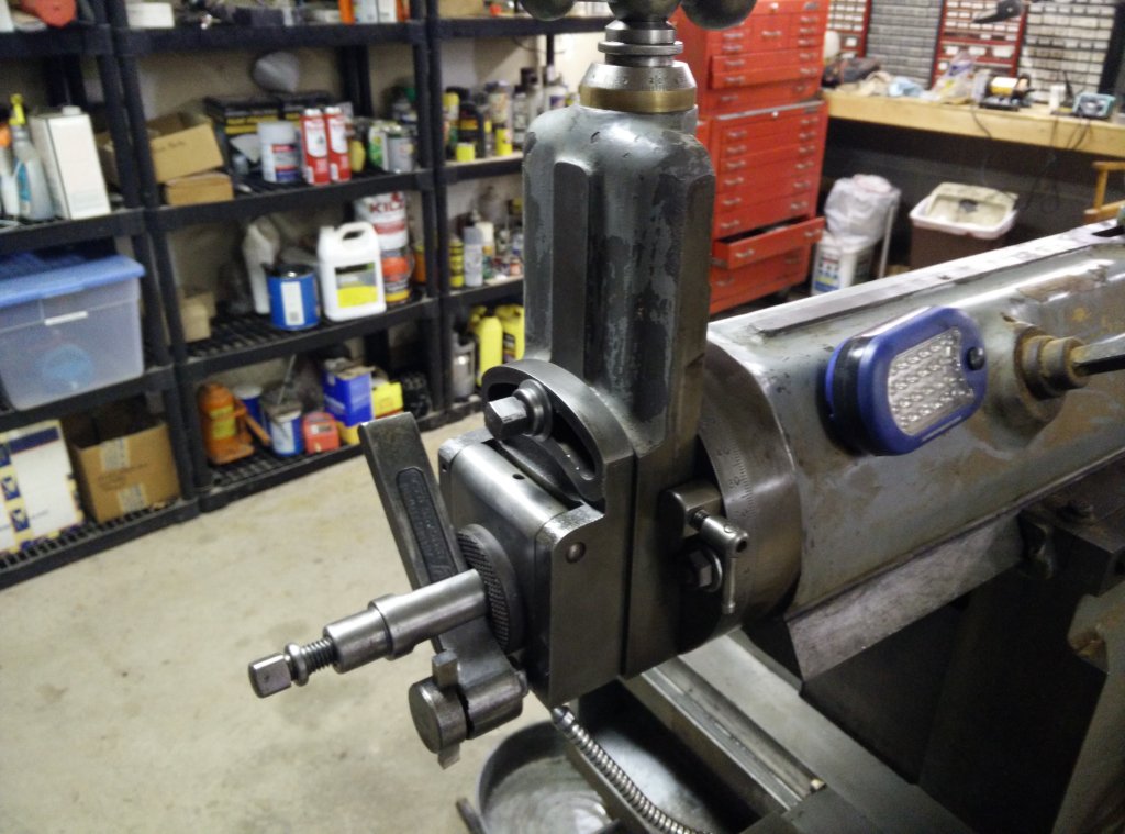 |
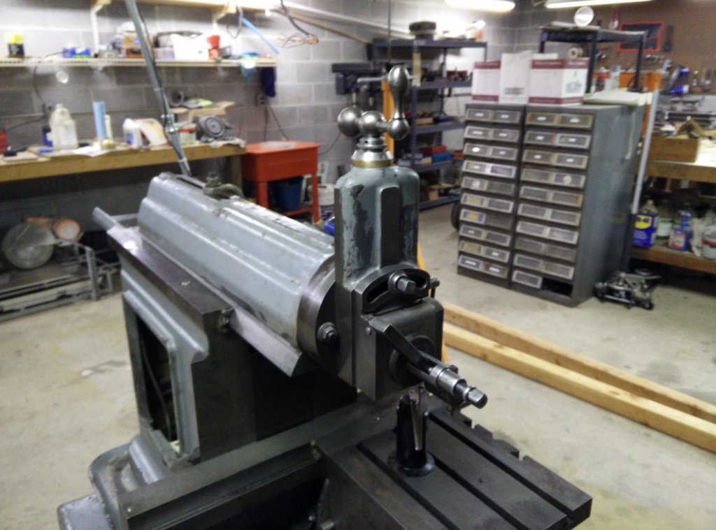
| The
down-feed tool slide, tool head holder, and clapper box
have been cleaned and oiled. |
The
tool post and tool holder are in pretty good shape. I
received 2 holders and want some more. |
 |
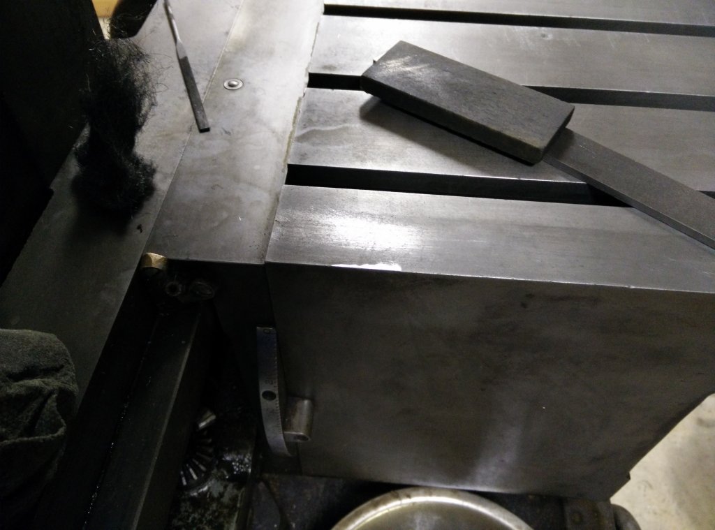 |
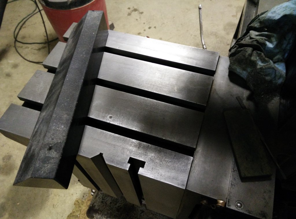
| Using a
small straight edge to detect some dings and raised areas
on the shaper table. |
With
the help of the a couple files and a fine stone, I knocked
down the ding on the near side of the table. |
The observation that a
straight edge will pivot around the Airy points is something
that I have noticed during many pivot tests while scraping flat
surfaces. The pivot point may not exactly coincide with the Airy
point, but it should be close. If the straight edge pivots at
any point other than the opposite Airy point, then there is a
high spot somewhere on the surface and the surface being checked
isn't flat. In general, if the straight edge pivots around the
center, the surface you are testing is convex and if it pivots
from the opposite end of the straight edge, the surface is
concave. A piece of swarf or grit under the straight edge will
make the straight edge pivot on that piece of swarf, so clean
tools and table are a must. If your straight edge is longer than
the table and the table is flat, the straight edge will tend to
pivot at about 1/4 of the table's width on the opposite side
from where you are pushing. By being able to interpret the way a
straight edge pivots on a surface, I find that I can easily get
a pretty good read on how flat a surface is. In the case of this
shaper table, it is pretty flat.
In the left picture above, you can see a divot to the right
of the straight edge. The straight edge pivoted around this divot
because the metal around the divot had been pushed aside and up
when the divot was made. I stoned this area flat and you can see a
shiny ring around the divot where I removed some metal. At some
point, I will ink up a surface plate and do a more complete job of
checking the table for flatness, but at this point, I just want to
get the machine's table clean and reasonably flat to test the
shaper's operation and get a general idea of its accuracy.
 |
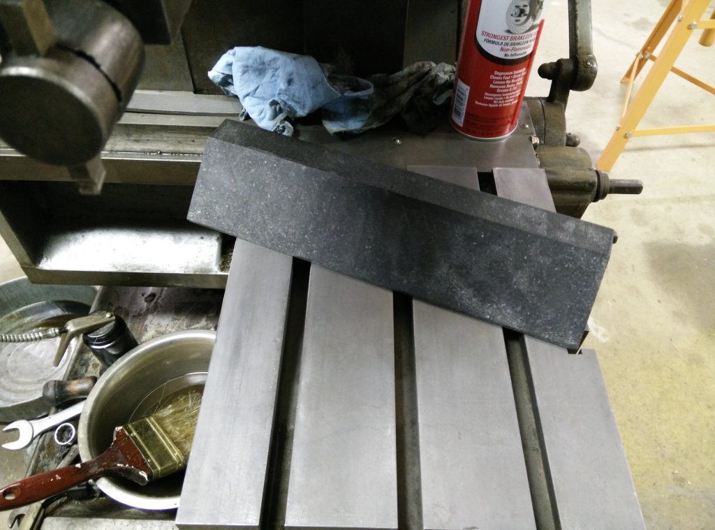 |
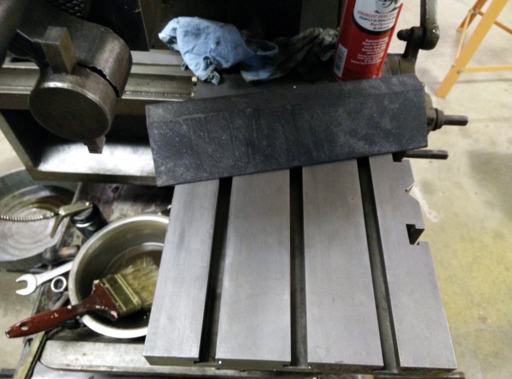
| With
most of the dings taken care of, I try a pivot test to
search for more high areas. |
Since
the granite is pivoting around a point about 25% of the
table width, the table is pretty flat. |
Three nights of
cleaning were needed to remove enough grime to be able to see the
cream colored paint that covers the inside of the base. It doesn't
look like the inside of the shaper had been cleaned in a very long
time. I went through about a gallon of mineral spirits, wore out a
4" paint brush and shortened the bristles on a soft stainless
steel brush just trying to get the mixture of oil, grease, dirt,
and sawdust, out of the base. On the plus side, I did find a
couple zerks (grease fittings) that I hadn't seen before. I gave
each of these a couple pumps of some good quality NLGI #2 GC wheel
bearing grease. The only manual I have for this shaper shows
exploded parts views and has a little information on lubrication.
The information specifies NLGI #2 bearing grease with a melting
point of 200 degrees F. NLGI refers to the National Lubricating
& Grease Institute. The #2 refers to the thickness of the
grease. The fact that the manufacturer specifies bearing grease
makes it type G. In automotive applications, type G is for wheel
bearings and type L is for ball joints and other suspension
components. Grease also has a rating for severity of service (A,
B, or C) A is for the least severe service and C is for the most
severe. For this shaper, since it won't be fording rivers or
participating in the Dakar Rallye, any of the severity ratings
will do, though I happened to have type C on hand.
To summarize the
shaper's lubrication needs, there are only 2 types of lubrication
that are specified for this Sheldon/Vernon shaper. The NLGI #2 for
all of the Zerk fittings and oil for all other lube points. For
the oil, the specs from the parts manual are "Use a neutral
mineral oil, viscosity 250 to 300 seconds at 100 degrees,
approximately SAE 20". This is a pretty close match to Mobile
Vactra #2 way oil which is ISO grade 68, SAE grade 20, 350 seconds
at 100 degrees F. If you buy the "house brand" at
McMaster-Carr, the SSU (Saybolt Seconds Universal) rating is 300
seconds at 100 degrees F. That's a perfect fit. Either one would
be a darn good match.
 |
 |
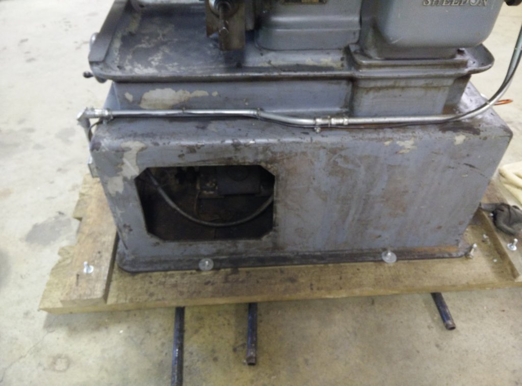
| The
outside isn't that dirty, but it isn't exactly
that clean either. Wait until we look inside. |
Inside
the base, it's another story. That's a 1/4" of dried oil,
grease, dirt, and sawdust on the floor. |
 |
 |
| It took
lots of mineral spirits and scrubbing to get the base
floor to this point. |
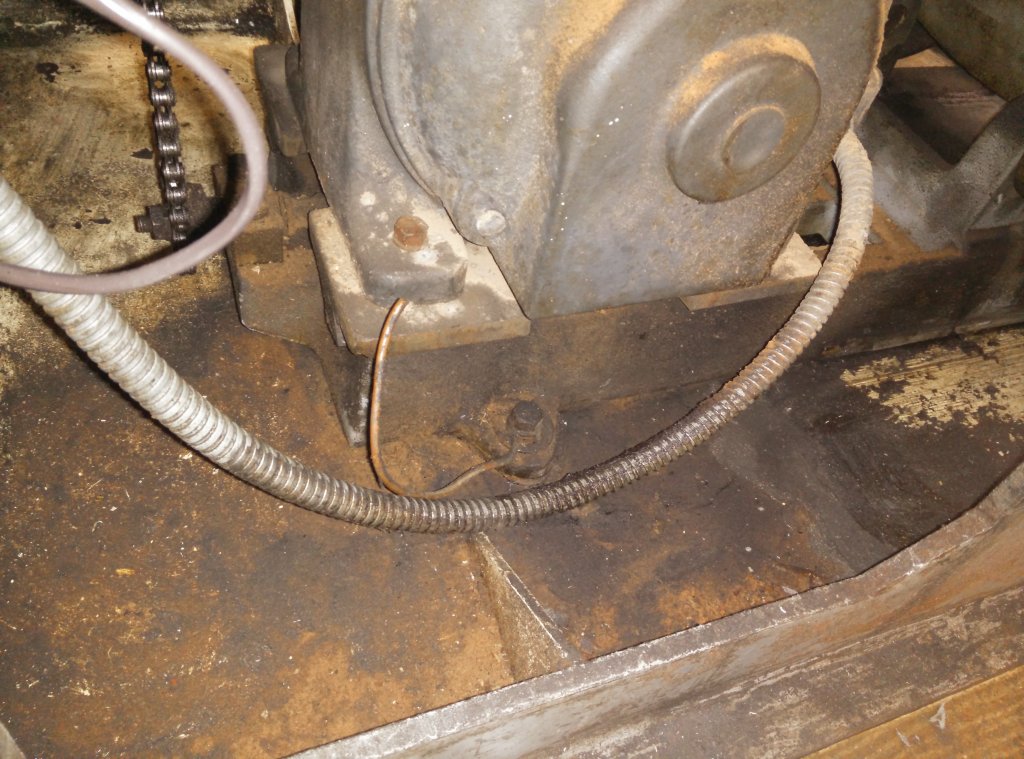
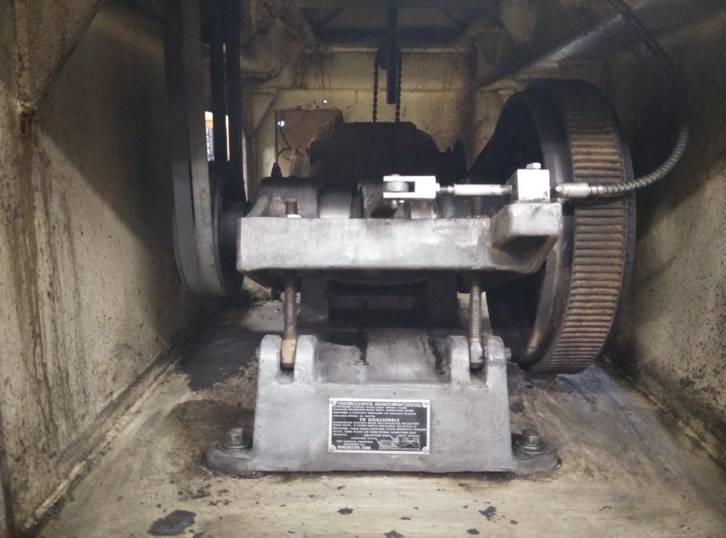
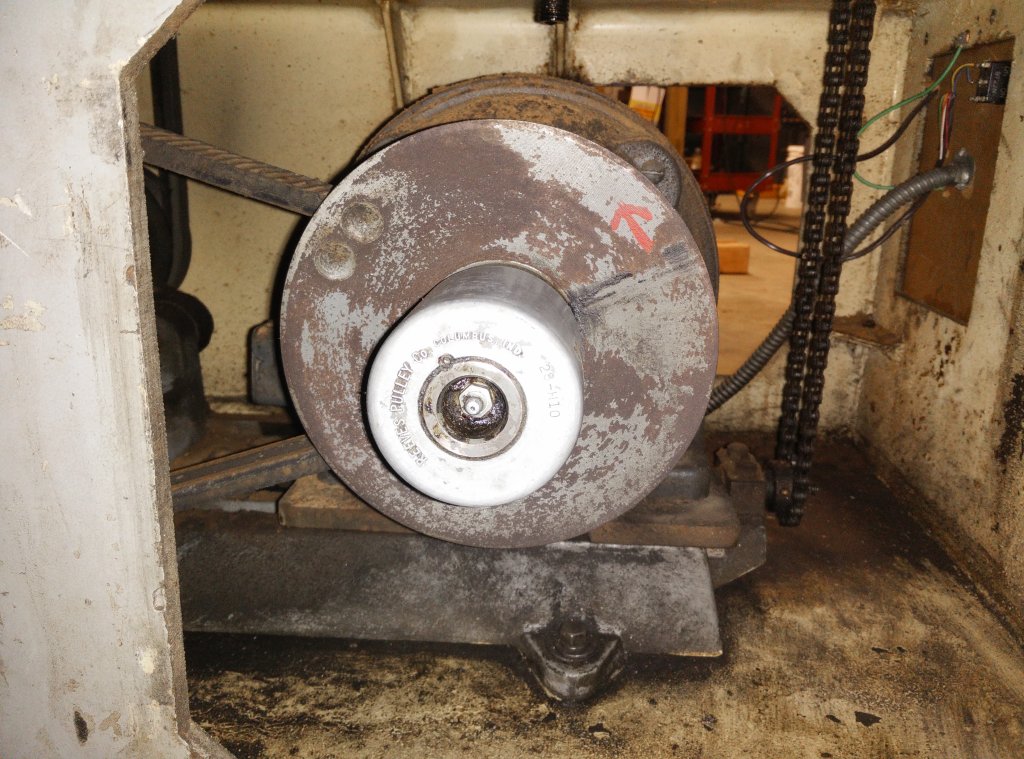
The
Reeves drive. To get all of the surface rust removed, I'll
need to pull this assembly out. |
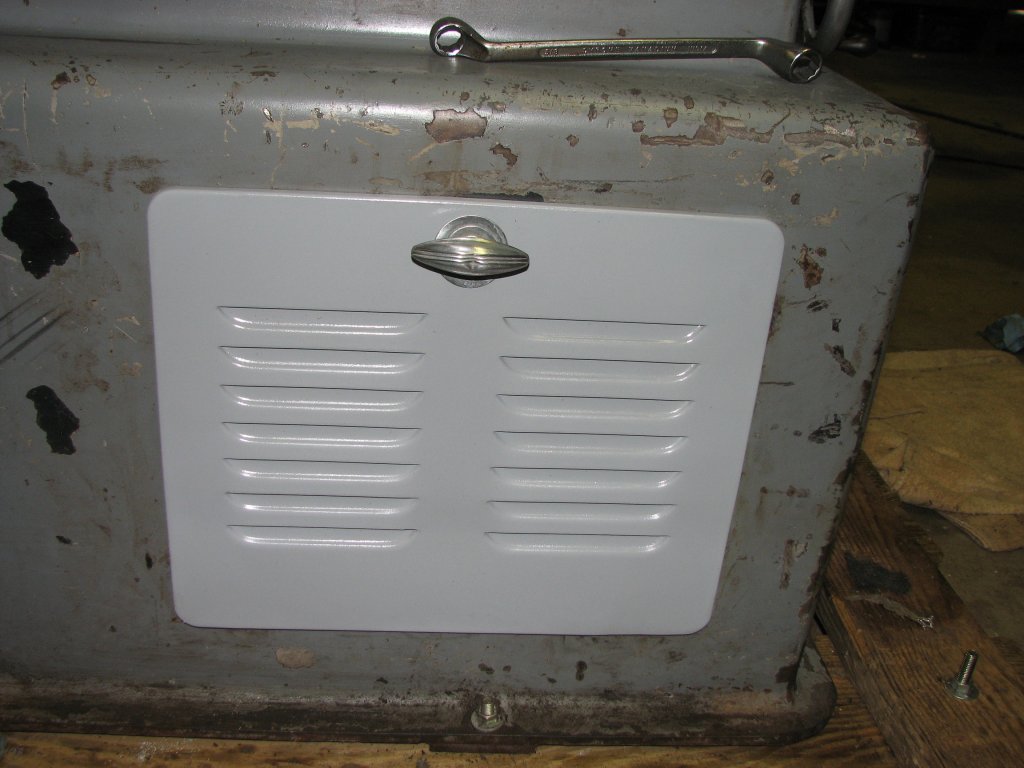
As I noted, the
shaper is missing the original switch plate from the front of the
machine. There is a 6.25" wide by 9.0" tall cut-out to the right
of the Sheldon/Vernon name plate. This has been covered over by a
piece of MDF with a small toggle switch and electrical junction
box that the previous owner had hooked up to a VFD to power the
3-phase motor from single-phase 240. He had run electrical conduit
out of the box and across the right side of the base. He did a
decent job of wiring it, but I wasn't really happy with the
conduit running over the top of the machine's base. It also
appeared that some other past owners had one had run the power
wires through the base and out the rear of the machine. Another
had run the wires out the side This was accomplished by cutting
rectangular pieces out of the side and rear panels. Again, not my
idea of the best way to do a clean job, however, I preferred that
approach better than having the conduit run over the base. For the
time being, I will rewire the machine with the conduit hidden
inside the base and exiting through the cut-out in the rear panel
until I can figure out how the wiring was meant to be routed.
Rather than keep
the 7" by 10" MDF in the front of the base, I cut some 1/4" thick
6061 aluminum sheet to make a new switch plate. I radiused the
corners, bored a 1" hole for the new switch, gave the new plate a
good sanding, and gave it a few coats of primer. I followed that
by a giving it a couple coats of clear enamel. Primer alone
wouldn't last very long in an oily environment. If I decide to
strip and paint the shaper, I'll sand off the clear coat and shoot
the new color over the primer.
 |
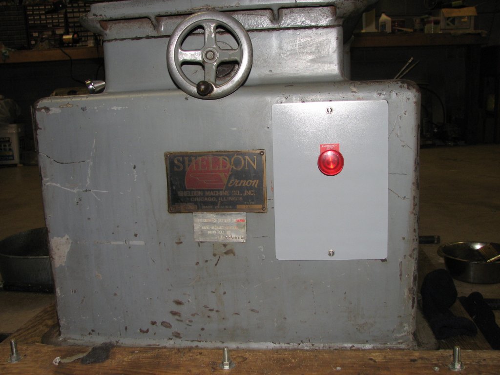 |
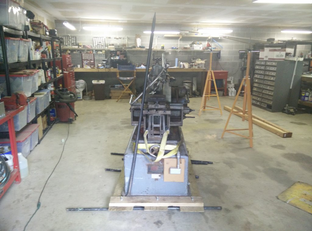
| The old
switch plate. This picture was taken after unloading the
shaper off of the trailer. |
The new
switch plate. The small plate below the Sheldon plate is
from a naval ordnance station. |
I installed an
emergency shut-off type switch in the new panel that will hook
into the VFD and serve and the power switch. This is a big red
"push to disconnect" switch. The on/off switch controls the WEG
CFW-10, 7.3 Amp variable frequency drive that also came with the
shaper. In addition to the on/off switch, the shaper has a manual
clutch which disconnects the ram from the Reeves drive. Since the
clutch lever is located on the right side of the machine along
with the other controls, it should be always within reach when
operating the shaper. The clutch is the best way to stop the ram
if something should go wrong, but kicking the big red button is
now another option.
Since the shaper has a Reeves variable speed drive to control the ram speed and also has a reduction gear for "back gear" type speeds, the previous owner had set up the VFD to just perform a soft start - slowly ramping up the frequency from zero to 60 cycles per second. For simply turning the VFD and shaper on or off, there's only one switch needed. While in theory, I shouldn't really need to use the variable frequency function of the VFD, having the ability to tune the frequency and thus control the speed can be helpful to get rid of vibrations when you are trying for the best possible finish. With this in mind, I mounted the on/off switch 2/3 of the way up the new panel. This left room for a potentiometer to be mounted below if I needed it for speed control. The frequency can also be controlled by the keypad on the VFD.
 |
 |
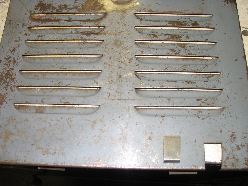
| The
cut-out that needed to be fixed and the new piece of sheet
metal that was cut and bent to fit into the existing hole. |
The
panel has been sanded to remove the paint. The piece of
sheet metal has been fit in place and clamped for silver
soldering. |
As I said, one
of the side panels and the rear panel had been notched. I am
assuming that this was done at different times to route the power
wires. As I was going to run my conduit out the notched rear
panel, this one didn't bother me. The notch on the side panel,
which would be more visible, bothered me. I figured that now was
as good a time as any to fix the side panel.
I had some 16
gauge sheet steel that happened to be the same thickness as the
door panel. I cut a piece and filed it to fit, then made the bend
using a shop vise as a metal brake. I bent the piece over the
rounded edge of a piece of scrap metal so that the bend would
match the bend in the door panel. Since I was going to silver
solder the patch in place, both the patch and door needed to be
clean metal. I sanded the door and patch piece and made sure that
the patch fit tightly, then applied lots of flux and did a little
silver soldering. To finish the job, I filed down the welds, hit
the door with a couple grits of sandpaper with the orbital sander,
then gave it a few coats of paint. The door came out nice and you
would be hard-pressed to find where it was repaired. By the way, I
really like the art deco handles on the access panels. A couple of
them have some dents, but if I decide to rebuild the machine, I
think I can take the handles apart and work them back to their
former glory. However, I am getting ahead of myself.
 |
 |
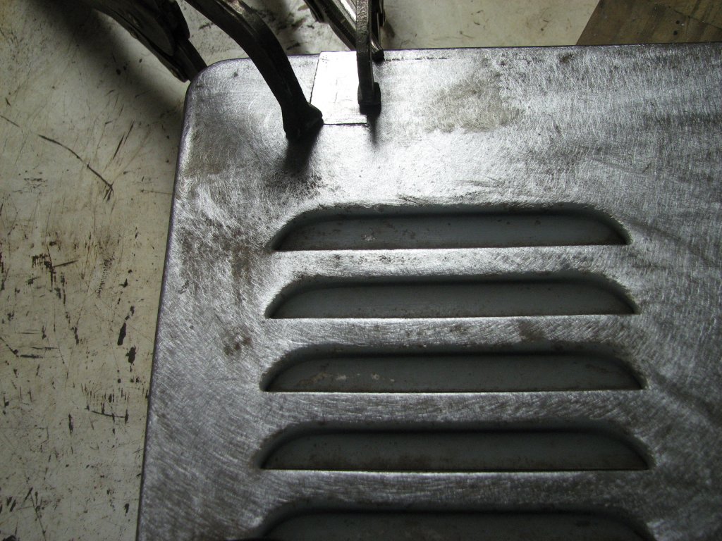
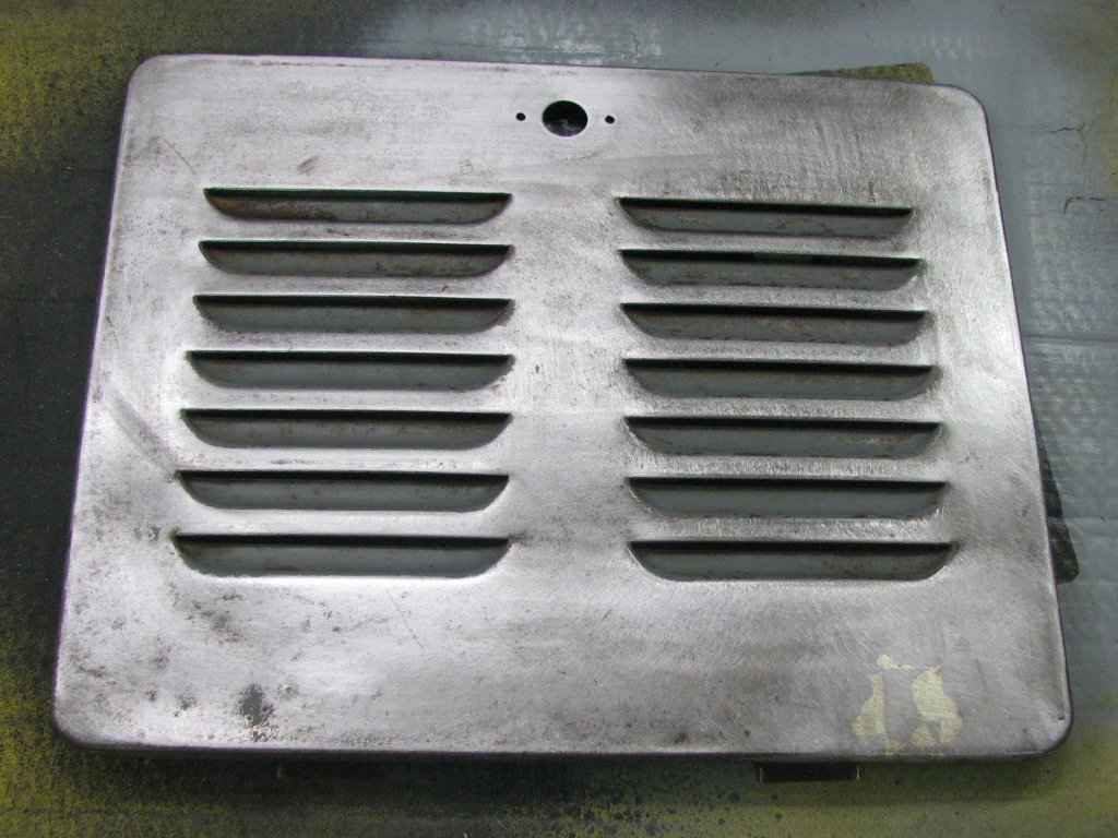
| The
silver soldered repair has been filed and sanded to blend
it in to the panel. |
A
couple coats of primer and a couple coats of clear and the
door is whole again. |
With the
cleaning done for now, it was time to build some adjustable feet,
move the shaper into its new location, and wire it up.
I considered
bolting the shaper to the shop floor, but I am unsure if where I
am putting it will be its final location. Once I make enough room
in the separate side loading stall that I use for tractor and
implement storage and also houses my woodworking table saw, I
would like to move the miter saw and eight foot bench that it's on
into that area. One room for wood and one for metal is my eventual
goal. I am getting really tired of cleaning sawdust off of my
metalworking machines.
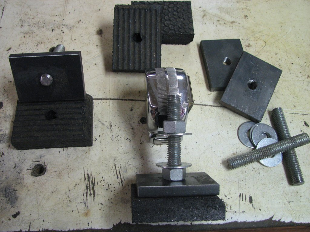
I have built a
few sets of adjustable feet for other machines, but not for a
machine that tends to walk itself across the floor like shapers
have a habit of doing. I thought I'd try using some of the one
inch thick "horse stall mat" on the bottom of the metal pads to
hopefully give them some traction on the slick shop floor. I got
the mat from a local farm supply store a few years ago and cut a
long strip to attach to the bottom of my smaller snow blade when
we still lived in a home with a paved driveway. It did a good job
of protecting the driveway from scrape marks. I now have the
remainder of the mat on the shop floor in front of the lathe and
nibble off pieces when I need some for a project. Since the shaper
will put a side load on the feet, I thought I would not only glue
the mat to the bottom of the 3/8" thick steel pads, but I'd also
run the all-thread through the steel pad and into the rubber mat
to try and keep the metal pads from sliding off the mats. I
roughed up the bottom of the pads and cleaned the tops of the mats
with brake spray and then glued them together with construction
adhesive. We'll see how that works.
 |
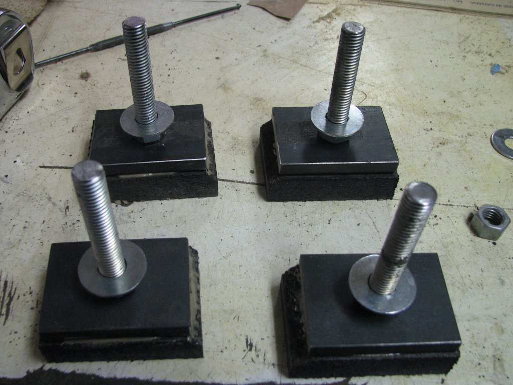 |
| The
feet are assembled from 2" X 3"X 3/8" steel and 1/2"-13
all-thread. |
The
feet are assembled and the mats have been glued to the
bottom of the metal pads. |
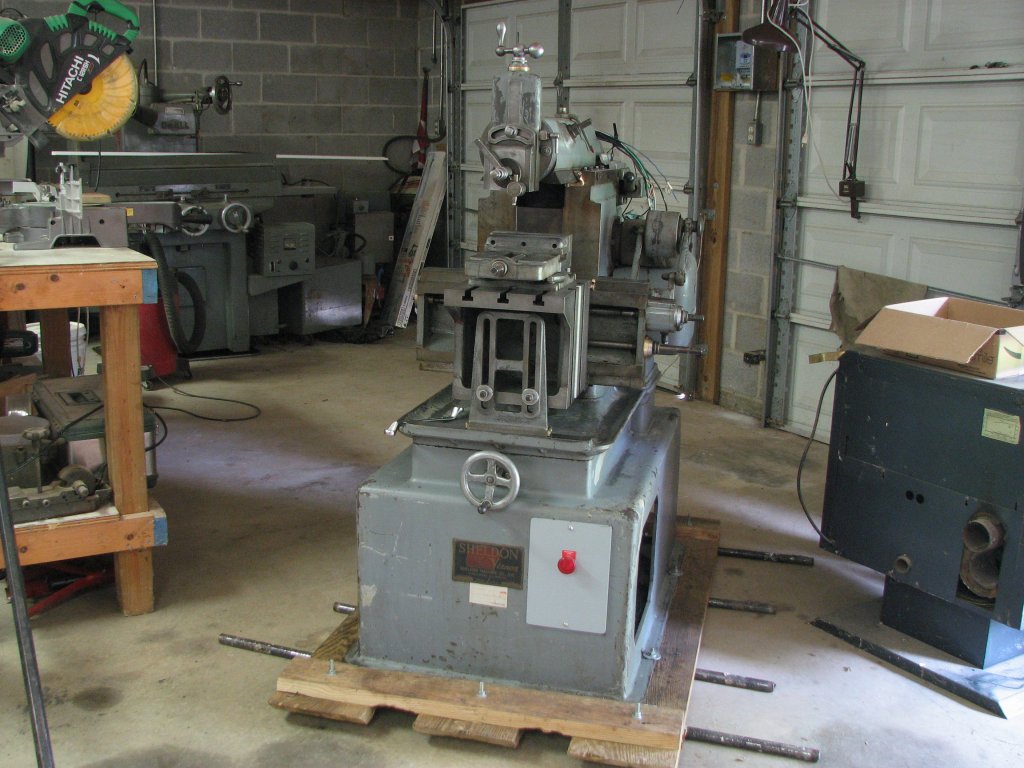
With the feet assembled, it was time to move the shaper into location. I needed to spin the shaper 180 degrees to get it headed in the right direction, then roll it across the floor using a Johnson bar and pipes. When I got the shaper to its new location, I used my make-shift gantry crane to lift it, remove the skids, then set it down on the new leveling feet. As I said in the last article on moving this shaper, this gantry has been one of my better purchases. It took less than 15 minutes to lift the shaper, remove the skid, install the feet and place it back on the shop floor.
With the shaper
in place, it was time to level it. My shop was originally built as
a four stall garage with a narrow room separating the three stalls
I use as my metal/automotive shop from the side loading end stall
I use for housing my smaller tractor and woodworking stuff. Since
the building was built as a garage, the concrete floor has a
slight slope toward the garage doors to help move any water to the
outside. This slope is a little steeper near the doors. As I began
to level the shaper, I found that the rear (garage door side) was
lower than the front by at least a half inch. Having to crank down
the rear adjustable feet means that the rear of the shaper is
going to be supported by more of the 1/2" diameter all thread than
I had thought. I am already thinking that I should be using
wedge-type adjusters to give the shaper a more solid base. I guess
I will find out when I run the shaper for the first time. Making
up some wedge-type adjustable feet might be a good first project
for the shaper.
 |
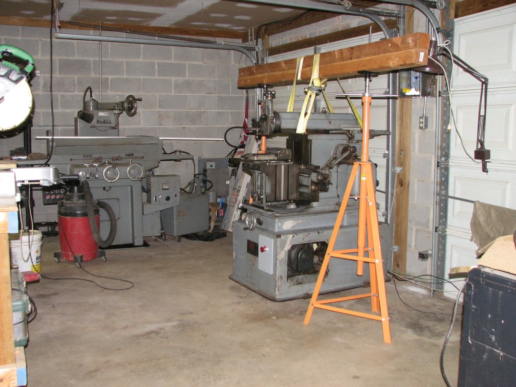 |
| Rolling
the shaper into position. I need to hook up that pellet
stove (right) before winter comes again. |
The
make-shift gantry crane made easy work of lifting the
shaper the needed four inches. |
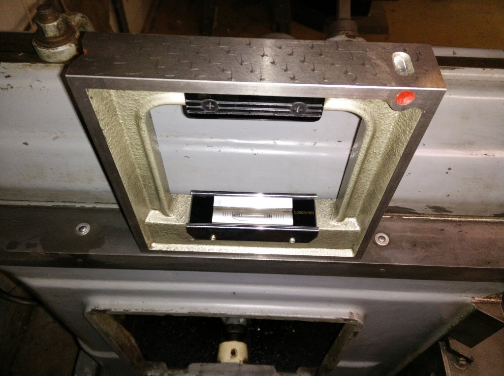
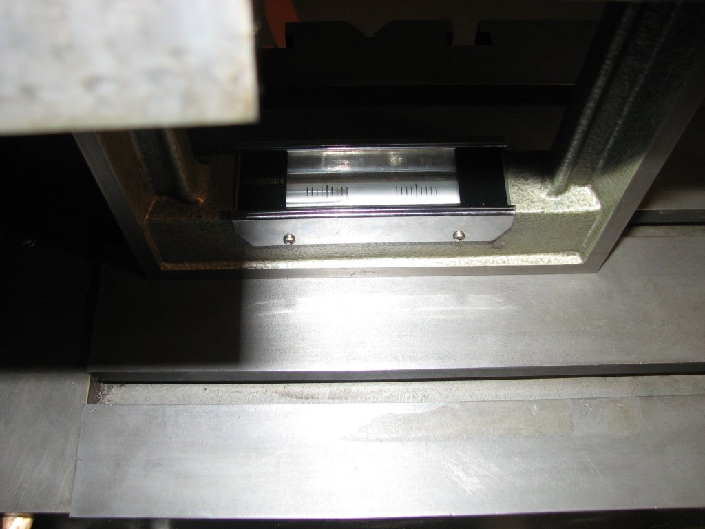
To level the
machine, I set my 0.0002" per 10" resolution box level on the
shaper table and did my initial leveling diagonally. I didn't know
if the shaper's tilting table was set plumb to the machine or
whether the table had succumbed to gravity and was low on the
operator's end, but it's a lot easier for me to level a machine by
adjusting the diagonally opposed feet rather than side to side and
front to rear and the table was the only place large enough to
place the level diagonally. Once I got the adjustments close, I
switched to using the machined casting that supports the left side
ram dovetail for the front to rear level and using the cross rail
for the side to side level. Yes, I tightened up the gibs before I
did this. With the shaper leveled within one graduation (0.0002")
in both planes, I checked the table level. The tilting table was
about two graduations low on the right side even though the
pointer was lined up on zero. The pointer is adjustable, so this
is an easy thing to correct. A bit more concerning, but not
unexpected, was that the front of the table was lower than the
rear by about four and a half graduations, which is about 0.001"
per foot.
I will have to
double check my "Machine Tool Reconditioning" book by Edward F.
Connelly, but I don't think he has a chapter on shapers. However,
from studying his other examples with movable tables, I am
guessing that the table actually wants to be a little high on the
front to compensate for wear and the deflection that the table
will see when the shaper is in operation. Milling machine table
ways are scraped in or ground to be up to 0.001" high on the front
of the table (Y axis). However, since there is a support under the
front of the shaper table, I may be wrong and the table may want
to be set parallel to the ram. This is all just a mental exercise
at this point. Before I start thinking about making changes in
adjustment, I need to try squaring a block under power, as I do
not know if the ram is even in the same plane as the casting I
used to set the front to rear level. I also don't know how worn
the ram bearing surfaces are. Hopefully some test cuts will give
me a lot more information than I have now.
Update: I was
able to get a copy of "Testing Machine Tools: For the Use of
Machine Tool Makers, Users, Inspectors and Plant Engineers"
- 1978 by Georg Schlesinger (Author), F. Koenigsberger (Author),
M. Burdekin (Author). This book has a section on testing shapers.
The test requirements for the ram being parallel to the plane of
the table top is listed as being between zero to 0.015mm per
300mm, which works out to be from about zero to 0.0006" per
foot with the provision that the table should be raised in the
front. This confirms my suspicions that the shaper setup is
similar to a milling machine. I am now pretty confident that I
will need to do some work to get the front end of the table to be
a bit higher, but I still have a lot to do before I reach the
point of actually making those adjustments.
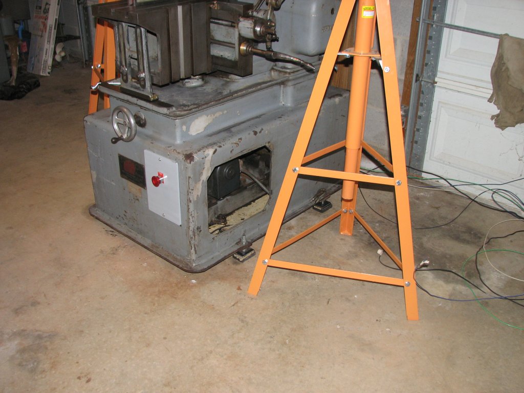 |
 |
| The new
feet are installed and it's time to get to leveling the
shaper. |
Checking
the level along the top of the cross rail. I am using a
0.0002" per 10" box level. |
I finally got
the shaper wired up and turned it on for the first time. I checked
to see which direction the Reeves drive pulley was turning. It
turned counter-clockwise when looking at the pulley from the left
side of the machine. This is the correct direction to allow the
ram to move slower on the cutting stroke and faster on the return
stroke. If it would have run backwards, it is a simple matter to
swap any two of the three leads from the three phase side of the
VFD to the motor, but I got lucky. I turned the speed control
wheel all the way to slow and pulled the clutch lever out. The ram
engaged smoothly and the machine was under way. I turned the speed
control to speed up the ram strokes and noticed a slight ticking
or knocking noise coming from the area of the sliding block or top
link once I got to about half speed and above. I would check into
the noise little further soon, but wanted to check the so called
'back gear' operation first. The speed reducer was called a back
gear by Sheldon, but it really isn't in the true sense of the
term. It is comprised of a couple of planetary type reduction
gears and I had read that most all of the Sheldon shapers were
noisy when running with the speed reduction engaged. I enabled the
reduction gears and ran the Reeves drive from the slowest to the
fastest setting. Yeah, the reduction gears are a bit noisy. They
are straight cut spur gears in a housing that seems to amplify the
sound of the gears meshing. It sounds a lot like my South Bend
lathe in back gear. It has a definite whirring sound, but nothing
that I was concerned about.
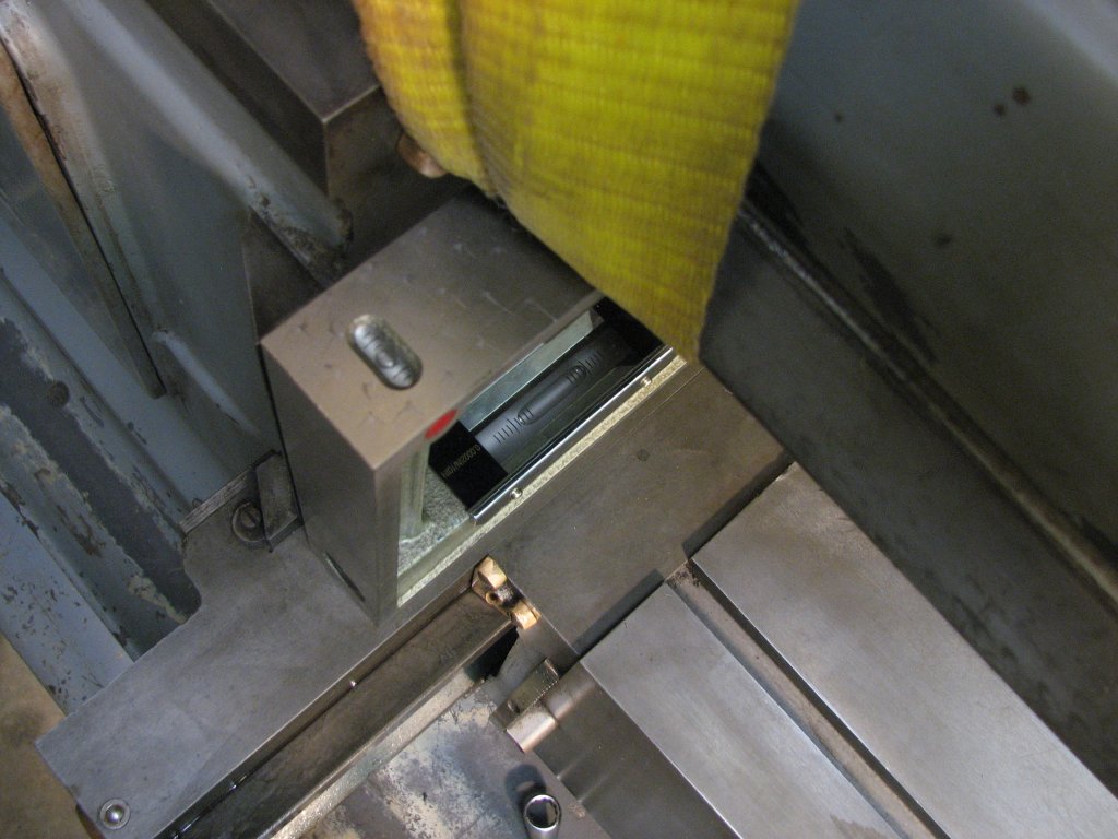
 |
 |
| Checking
the front to rear level on the casting that encloses the
left side ram dovetail ways. |
The
operator end (front) of the shaper table slopes down about
0.001" per 12". |
I grabbed a
chunk (4"X 3"X 6") of cast iron from my scrap box and mounted it
in the vise. I set the stroke to be about an inch longer than the
4"width of the chunk of iron and set the ram to start its stroke
about a half inch before the stock, then manually turned the
Reeves drive pulley until the ram passed the stock and started its
return stroke. I made sure that this was about a half inch past
the end of the stock. Running the ram by hand let me know that I
wouldn't crash the tool bit or tool head on my first attempted
cut. That wouldn't be a good way to christen the shaper. I honed
the finishing tool bit and installed it in the tool holder and was
going to try a 0.005" depth of cut with a 0.010" feed. I thought
it best to take a light cut on the first attempt. I was quite
impressed with my first cut on a shaper. The shaper is very quiet,
much like a lathe. Just a sound like frying bacon as the bit
peeled off a thin layer of cast iron. The finish on the cast iron
was very smooth. It puts the finish produced by my milling machine
to shame. It is also fun to watch the cuts being made. My wife had
come out to the shop to ask me a question and saw the shaper
cutting. She found the rhythmic action of the ram pushing the tool
bit through the cast iron almost as interesting as I did. After
running the shaper for a half hour or so and getting used to
sounds it made while working, I decided that it was time to check
the sliding block fit again.
The bronze
sliding block is held in place by one 3/8"-16 tpi bolt. The parts
diagram shows that the bolt is supposed to be secured by a lock
washer, a machined flat washer, and an 1/8" cylindrical pin that
prevents the bolt from backing out. I pulled the pin with a pair
of end cutters and unscrewed the bolt. If the parts list I have is
to be believed, the lock washer was missing. However, given the
length of the pin, the lock washer would need to be very thin to
allow the pin to lock the bolt in place. I am thinking that there
was no lock washer on this bolt despite what the parts manual
shows. I think that this manual is for an older model than I
have.
I measured the
width of the sliding block where it fits between the ways of the
Scotch yoke and came up with a measurement of 1.7265". I used an
inside bore gauge to measure the inside of the Scotch yoke rails
and came up with 1.7280". With a 0.0015" difference between the
width of the block and the width of the yoke, there doesn't
appeared to be very much wear on the bronze block. I measured the
block in many different places and still came up with 1.7265".
There was also next to no wear on the yoke and what I assume to be
the original factory scraping was still very evident on the cast
iron surfaces that the bronze block slides against.
 |
 |
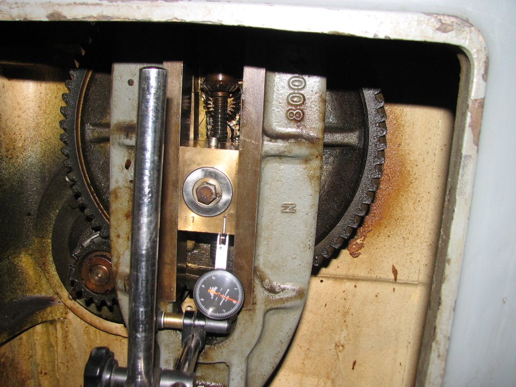
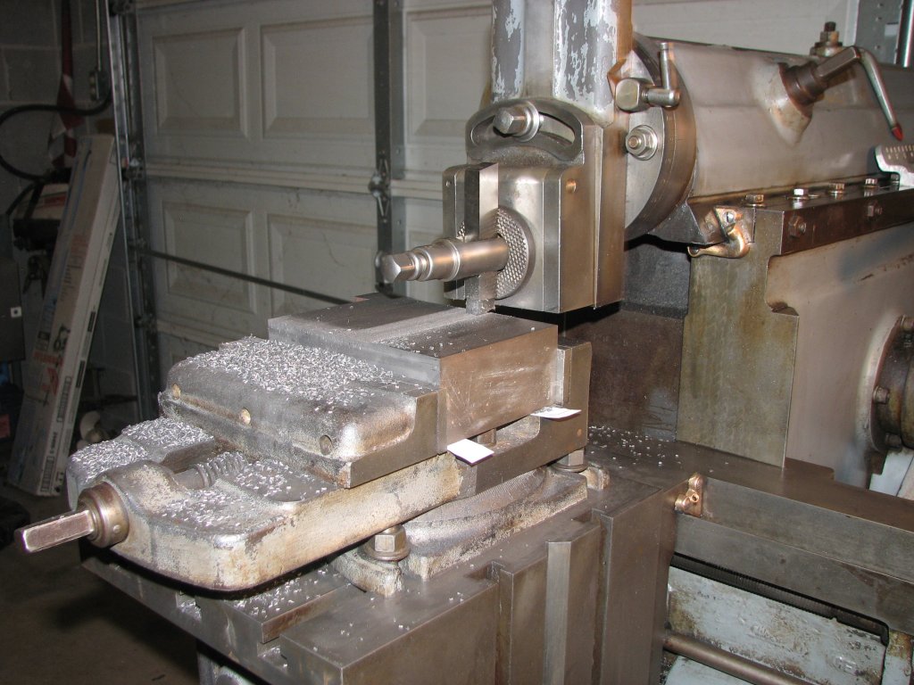
| Testing
the axial play between the bronze sliding block and the
sliding stud. |
The
pointer on the DTI has moved counter-clockwise a little
over six thousandths. |
I measured the cylindrical bore of the sliding block and came up with 1.127". The crank pin that the block rides on measured 1.125". I am guessing that when the shaper was new, there was a little less clearance, but 0.002" didn't seem like that much play. What I did find was that there was about 0.006" axial play where the sliding block bore slides along the crank pin. The Sheldon parts list calls this pin the sliding stud. With the bolt and washer installed, I could move the block axially - left to right when facing the front of the machine - about six thousandths of an inch. I noticed that there was a circular wear pattern on the rear of the sliding block where it contacted the sliding stud. I measured the wear and found that the recess was around 0.005". I figured that the best way to take up the play was to add a couple shims behind the sliding block to remove some of that 0.006" play. I ordered a shim assortment from McMaster - 3088A937. As long as I was placing an order, I figured that I should take care of the oiling felts. The sliding block has 4 round pieces of 5/16" diameter felt cord that spread the oil from the sliding block to the Scotch yoke rails. These felts were hard as a rock and might be original to the machine. It did not appear that much oil would get to the yoke rails in the felt's current condition. I ordered some 5/16" felt cord and also ordered a 1/4" thick felt sheet to make up some new ram way wipers. The old felts actually measured 3/16" thick, but they were compressed by years of use. By using 1/4" "F1" felt, I hoped to get good contact between the felts and the ram dovetail ways. Replacing the oiling felts is always a good idea.
I received the
shim pack and used a micrometer to measure out 0.005" of shims. I
installed them, reinstalled the sliding block, and measured the
free play. It was now at a little more than a thousandth. I pulled
the sliding block back out and cut some of the new 5/16" cord to
replace the hardened felt oilers. I oiled up the new felts
and installed them and then reinstalled the sliding block. I
removed the four wipers. Two from the front of the ram and two
from the top dovetail ways of the cross rail. To make a pattern to
cut the felt, I used the old oily felts on top of the new felt
sheet. I pushed them into the new felt and they transferred their
dirty oil in the shape that needed to be cut out. I added a bit of
width to each of the sides of the felts to allow them to be
compressed by the ways. Before I installed the new felts, I
cleaned off the dirty oil with some automotive brake spray. Time
to do some more cutting.
 |
 |
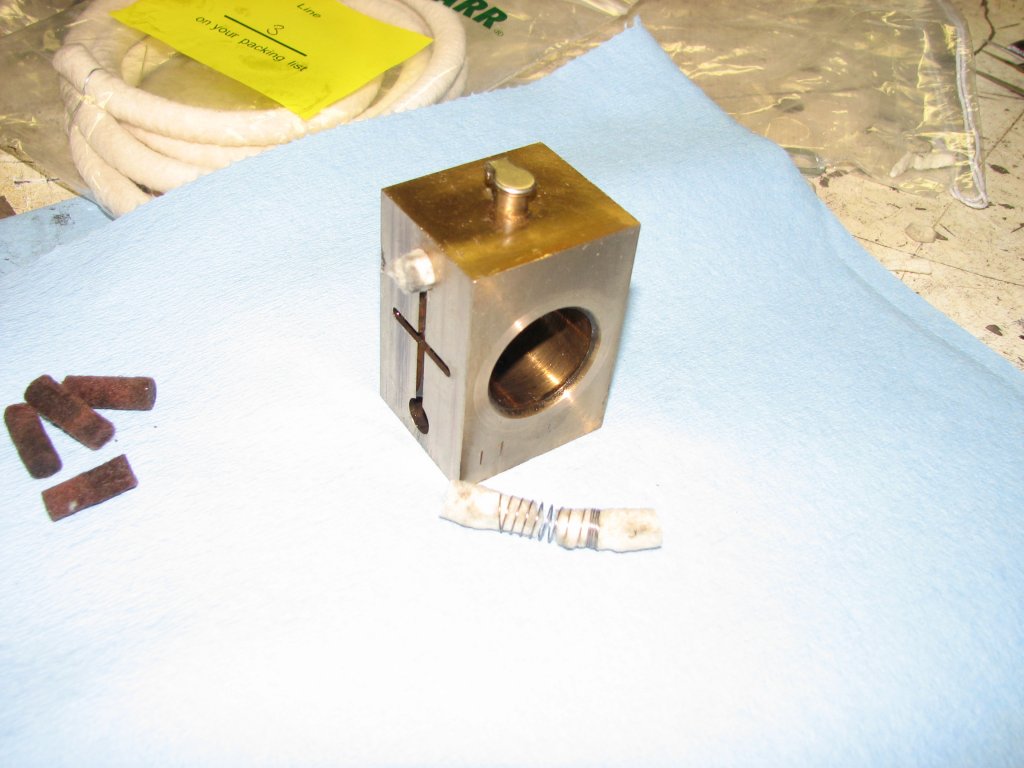
| The
5/16" felt cord has been threaded on to the spring. Once
the pieces were installed, I cleaned them with some brake
spray. |
The
1/4" F1 felt sheet has been cut by pressing the old oily
felt into the new piece, then cutting around the pattern. |
For my first
cut, I had used the tool bit that had come with the machine. I had
just honed it and put it to work. The bit was 1/4" wide X 3/8"
deep and was ground in the pattern of a cast iron finishing bit.
This bit was ground so that it presented a cutting edge at 90
degrees to the direction that the ram traveled. I had been reading
about shaper bits and holders and wanted to try directly mounting
a bit into the tool post without using a tool holder. I bought
some rectangular 1/2" X 3/4" X 4.5" long HSS tool blanks and
ground a bit that had a 5 degree shearing angle to the cutting
edge, a 5 degree top rake, as well as 5 degrees on the front and
side reliefs. This bit gave me an even nicer finish to my cast
iron block. For the next tool bit, I will try a larger shearing
angle for use with steel.
My first project
was to square up the cast iron block on four sides so that I could
assess how accurately I could plane surfaces. I had found about
0.001" drop over 12" in the front when I had checked the table
with a level. After carefully mounting the block in the vise on
some paper scraps, tapping it down while tightening the jaws to
make sure the work was fully seated in the vise, and then
proceeded to cut the first of the four faces. When I completed all
four faces, I moved the block to a surface plate I found that I
had about 0.0015" difference in height over the four inch front to
rear span. That's quite a bit in only four inches. However, the
next measurement was a lot better. When I measured the height of
the side to side cut, it was only off by about 0.0002" over 6
inches. This measurement is close to what I observed with the
level. The next step is to realign the tilt of the table using my
level. I will also remove the vise and put it on the surface plate
and check it for being parallel between the rails and base. Once
those steps have been completed, I will plane the surface of the
block again and check the results. Since I have very little seat
time on a shaper, I am trying to work one step at a time to see
what happens with each change I make.
 |
 |
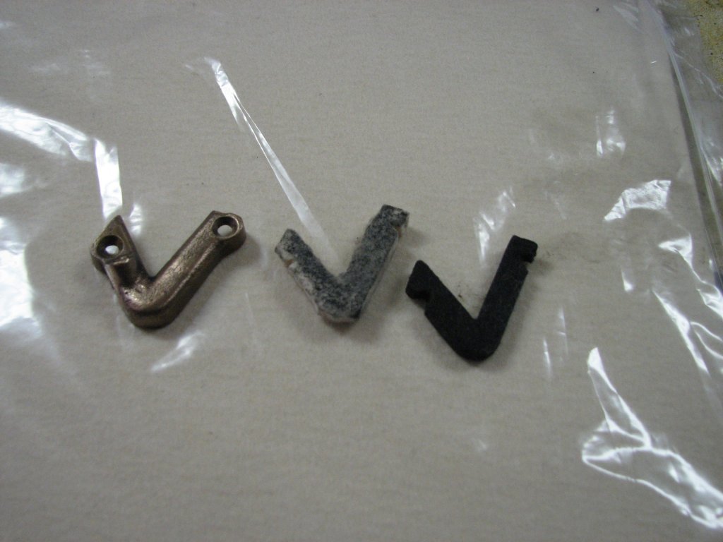
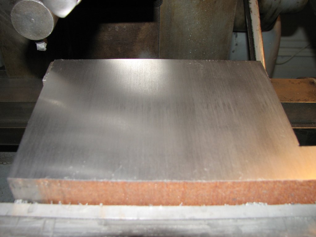
| The
first cut was made with a straight cut bit with about 3
degrees side and vertical clearance. |
Recutting
the top of the cast iron with a slightly shearing tool bit
mounted directly in the tool post. |
Well, forget the
last statement about the accuracy of the cut. Tonight I stripped
down the swivel vise and put it on the surface plate one piece at
a time. The block only came out as square as it did by chance. For
a machine that is probably 60 years old, I shouldn't be surprised
by the outcome, but I was. Nothing on this vise is square with
itself or the shaper table. The rails of the vise that support the
movable jaw aren't parallel with the bottom of the vise and the
supporting ring on the top of the swivel base is not parallel with
the base's bottom surface. When I pulled off the fixed jaw's
removable face, the rail under it was about 0.004" higher than the
rest of the rail on the right side and 0.002" on the left. The
rails were also not a uniform height from the base. The rails
varied in height by a few thousandths of an inch. I have never
seen the rails on a vise wear this much, so all I can think of is
that it has been poorly resurfaced at some point. I knew
that I needed to do some work on the vise jaws, but I didn't
figure I would have to rebuild the whole vise. I have some work
ahead of me. On the plus side, I haven't done any scraping since
we moved into this home a
few years ago and I've been wanting a scraping project. I can only
do home repair projects for so long before I want to get back to
working with metal. Now I have an excuse to pull out the scrapers.
The last time I
rebuilt a milling vise, it was an import and I found that trying
to get the swivel function to repeat with any semblance of
accuracy was hit or miss. I found that there's enough flex between
the vise and the swivel base that I don't use it unless I have a
specific need and am prepared to lose some accuracy. I now just
mount the vise directly to the table and keep the swivel base
wrapped up in a cabinet. Unfortunately, I can't mount the shaper
vise directly to the table without the swivel base. The table T
slots are on three inch centers (six inches between the swivel
base mounting bolts) and the vise mounting holes are on five and a
half inch centers. I will say that even in its current
state, the accuracy of this swivel vise is a lot better than the
import was before the rebuild, but putting the swivel base on the
surface plate and checking the ring that supports the base of the
vise was out by 0.0014" as I ran my 0.00005" resolution DTI around
the cylindrical mounting boss. I was hoping that there was a ding
or burr on the machined base that was causing the issue, but that
wasn't the case. I inked up a surface plate and marked the bottom
of the swivel base and found it to be a pretty nice job of
machining. No obvious high spots from the base being dinged or
dropped, but there were some low spots that I'd need to deal with.
If I had to guess how the bottom surface of the base was machined,
I would guess that it was turned on a lathe. There are concentric
circles that radiate from the center to the outside of the base.
The ink pattern from placing the bottom of the base on a surface
plate with a thin coat of Canode
marking fluid reminds me of a circular moire pattern. There were
some darker markings on the four outside corners - just past the
cut-outs for the four hold-down bolts - but scraping these down
did very little to change the relationship between the base and
the ring that supports the vise. Time to get out the Biax and do
some power scraping.
 |
 |
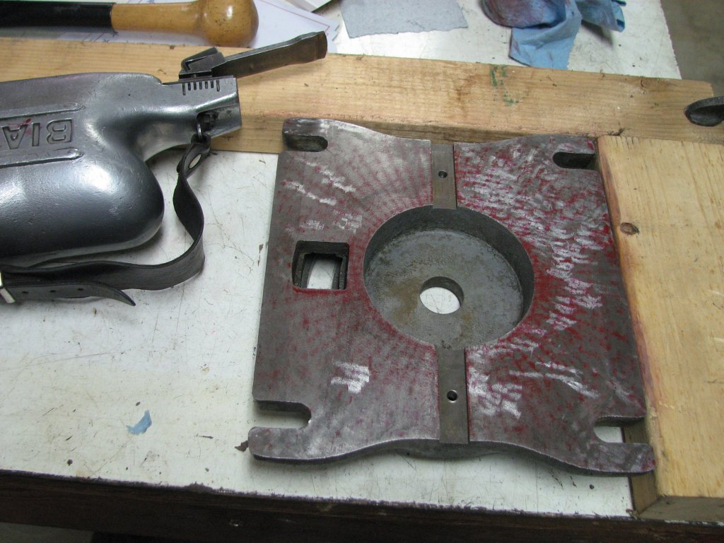
| On the
left side of the base you can see the pattern from the
original machining. |
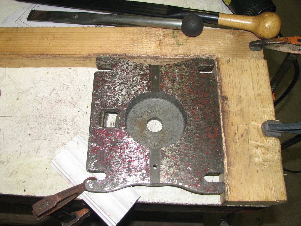
After a
few passes with the Biax scraper. The base shows color
across the whole surface. |
After a few
passes with the Biax scraper, the bottom of the swivel base was
showing color across the whole surface. The next step was to
refine the surface. I'm thinking that 20 - 25 points per inch will
be good for this surface. I cleaned the base and put it back on my
big surface plate and checked the ring that the vise mounts to. As
I suspected, it was still uneven. Since the ring sits lower than
the center boss that centers the vise, it wouldn't be easy to
machine the ring with the tools I own. The ring has a two inch
segment that is about a half-thousandth lower than the rest of the
ring. This area lines up with the the circular area shown in the
left picture below (right side, below the bolt hole). The only
reason that I can come up with for this is that the two mounting
bolts weren't tight enough at some point and the vise was rocking
on its swivel base. Since the movable jaw end of the vise is
unsupported, there would be a lot of force being directed at this
end of the vise base. I will use a file to get the ring close to
an even height, then scrape the bottom of the vise flat and use it
as the master to scrape the ring flat. When this is completed, I
will machine the vise rails parallel with the vise bottom and
base.
Speaking of vise
swivel bases, I've read is that having four bolts to mount the
swivel base to the table is one of the things that distinguish a
shaper vise from a milling vise. Milling vises normally only have
two bolts to hold the swivel base to the table. While the four
bolts certainly secure the base better than two, there are still
only two bolts holding this vise to the swivel base and it is this
connection that seems to introduce a lack of rigidity. I have to
admit that I don't quite understand the point of having four bolts
on the base and only two on the less rigid connection. While
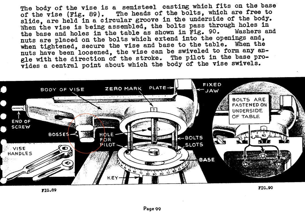
reading about shapers and shaper vises, I found a drawing from a 1940s
introductory course on using the shaper. The manual was
written to familiarize an apprentice with shaper operations as a
part of war materials production during WWII. One of the drawings
shows a vise that has a couple of bosses that help to support the
portion of the vise that overhangs the circular mount. (Expand the
picture below right.) I think that these bosses would add some
more rigidity to the vise to swivel mount junction and help to
prevent the wear I have found on the bottom of the Sheldon's vise.
I'm thinking that I could grind some blocks to attach under the
movable jaw side of the base to increase the rigidity.
 |
 |
| The
vise bottom isn't flat. Some color on the upper right and
a bit on the lower left edge. The circular mount area
below the bolt holes shows some wear. This will need to be
addressed. |
Drawing
of a pair of bosses on a shaper vise from a 1940s war
effort shaper user's manual. I like the idea of
these bosses to limit movement and the wear shown in my
vise picture on the left. |
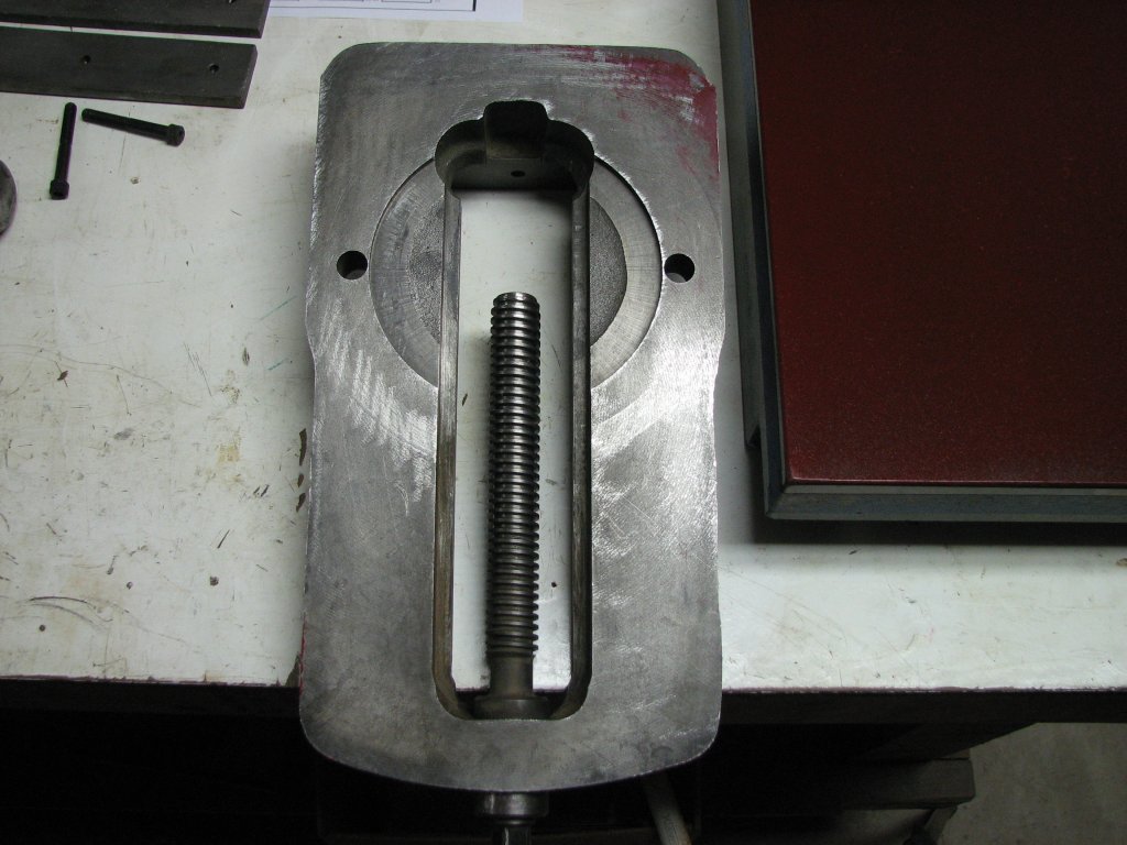
You'll notice
that in the picture above, the Acme screw has not been removed
from the vise body. There is what I assume to be a tapered pin
that holds the bearing collar on the screw. It appears that at
some point in the vise's life that someone has tried to get this
apart before. Both ends of the pin have been mushroomed above and
below the surface of the collar. I removed what I could of the
mushroomed heads with a file, then used a small drift to see if I
could get the pin to move. I wasn't able to get it to move at all.
Rather than take chance to doing more damage and having to drill
out the pin and ream the hole, I looked for another way to remove
the movable jaw. I found that by removing both jaw faces, then
screwing the movable jaw all the way toward the fixed jaw, the
movable jaw disconnects from the screw. If you then tilt the
movable jaw toward the screw, it will lift out. Since I can lube
the screw bearing without removing it, I will just leave the screw
in place as I scrape and machine the vise bottom and rails.
After another
night's work, I had scraped the swivel base to around 20 points
per inch. I also did a little more work with a fine file and stone
on the ring that supports the vise. I now measure about 0.00025"
difference between the high and low spots on the ring. My filing
has left the ring a little less parallel with the base bottom
surface than it should be, but I will now put it aside until I get
the vise bottom scraped flat. I will then use the vise bottom as
the scraping template to allow me to scrape the swivel base ring
to fit the vise bottom. Scraping the ring will allow me to bring
it back into full contact and parallel with the base.
I have been
giving more thought to adding bosses to the screw end of the vise.
I am now thinking that once the vise rails have been machined to
be parallel with the swivel base, I can place the whole
refurbished vise on the surface plate and use gauge blocks to
determine the thickness of the bosses. There is enough thickness
to the vise body to allow me to drill and tap some blind holes to
the bottom of the vise to mount the boss. I am thinking that one
piece of cast iron to straddle the bottom of both rails with the
center relieved so that there are two feet to contact the shaper
table. This will give me three points of contact - swivel base and
two bosses/feet - which should be about as stable as any design I
can think of.
The next step is to finish scraping the vise base, then to decide how I am going to machine the rails of the vise. Since the fixed jaw of the shaper vise is not removable like a Kurt style milling vise, it is a little trickier to machine the rails. The vise rails are nine inches long and my 24" surface grinder only has six and a half inches of cross travel. Due to the fixed jaw, I cannot grind the rails on the long axis of the grinder. I suppose I could grind it in two setups along the shorter axis of the grinder where the grinding wheel would be able to cut along the edge where the rails meet the fixed jaw, but having to do two setups is less than optimal. I could also grind the rails, then finish them by scraping or I could mill the vise rails and finish them by scraping. There is also the possibility of planing the rails on the shaper. That may be the best way to go, but I will need to do some work to get the table level so that I don't introduce more error into the vise. I'll have to think about this a bit more before I tackle machining the vise.
That's it for
now. I am looking forward to getting the vise sorted out and
getting to know this shaper a little better.
| Shaper 1 |
Shaper 2 |
Shaper 3 |
Shaper 4 |
Shaper 5 |
Shaper 6 |
Shaper 7 |
Shaper
8 |
Shaper
9 |
© Fager July 23, 2015