
|

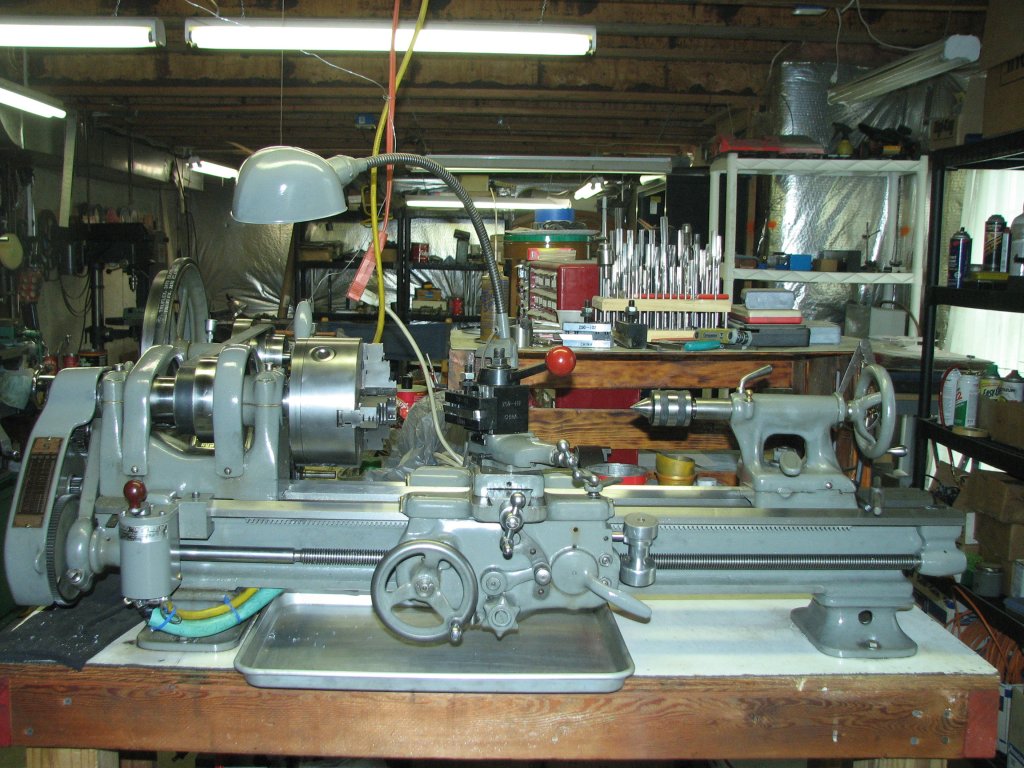 |
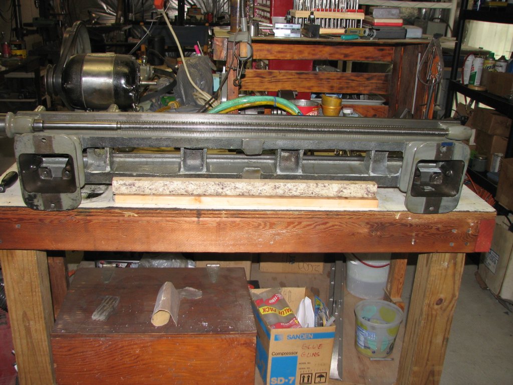
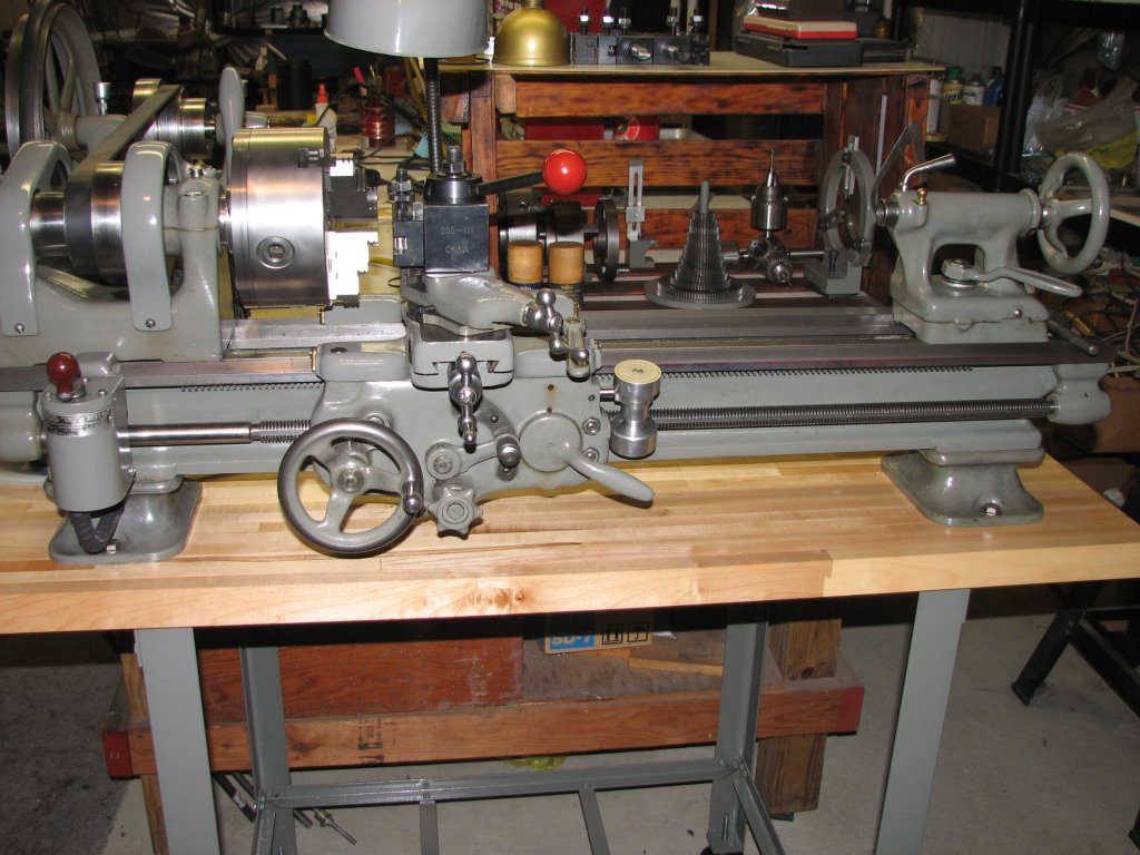
| Here's the lathe before starting
the most recent projects. The 405 has the later model A/B saddle
and apron
fitted, but not scraped in yet. The lathe chuck is a Bison
6". It's a nice heavy duty chuck. |
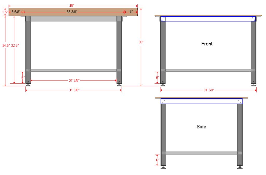 |
| Measurements for the SB 405
lathe bench. |
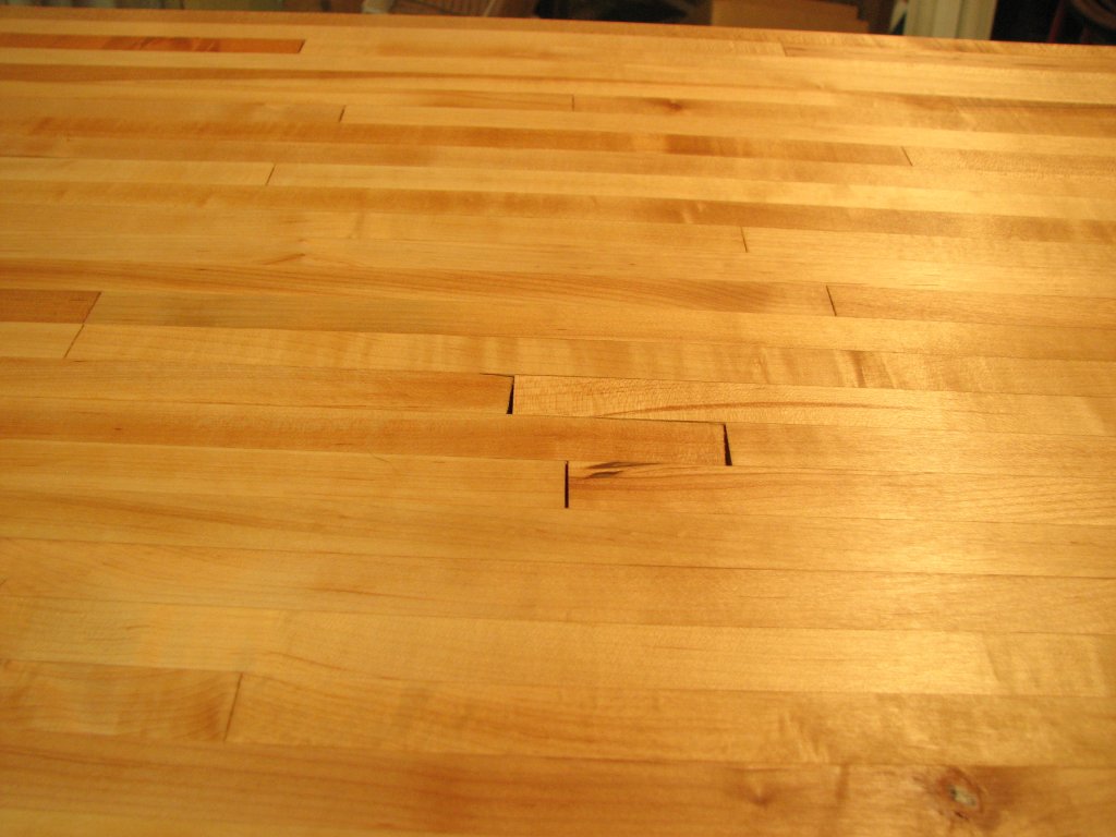 |
| Less than perfect joints on the
Williamsburg Butcher Block Co. counter top. |
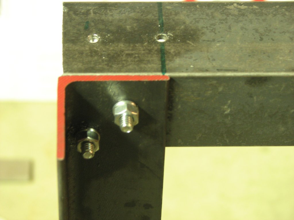 |
| Each joint has two bolts to
minimize movement. |
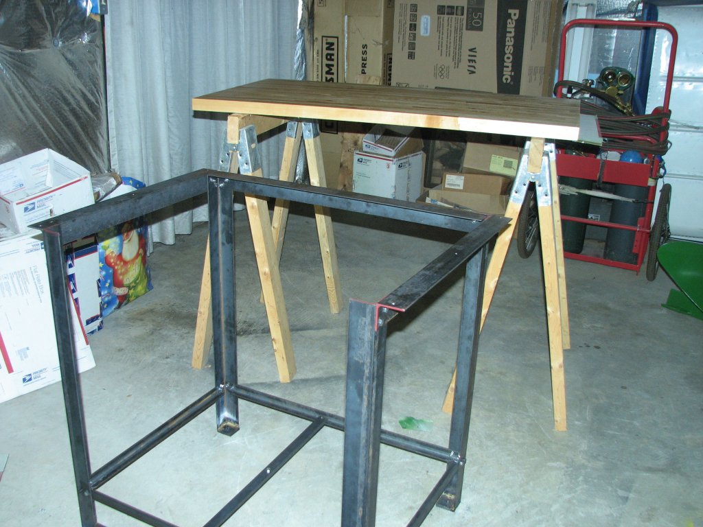 |
| Frame is assembled and butcher
block has had 3 coats of tung oil. |
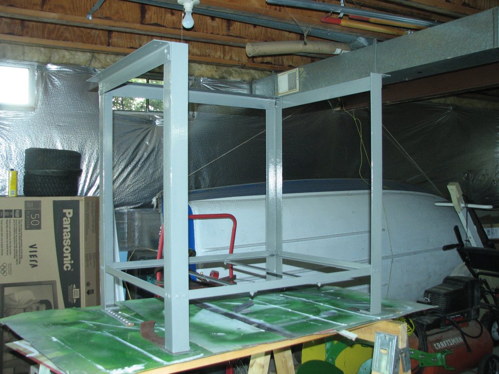 |
| The bench frame gets a couple
coats of paint to match the color of the lathe. |
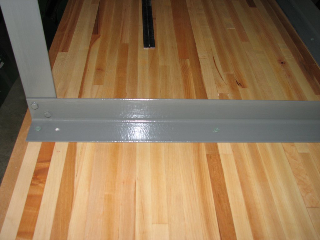 |
| The butcher block is attached to
the frame using backer board screws due to their holding power and nice
square drive. Why aren't all wood screws fitted with square drive
sockets like these? |
 |
| Getting ready to remove the
lathe bed feet. |
 |
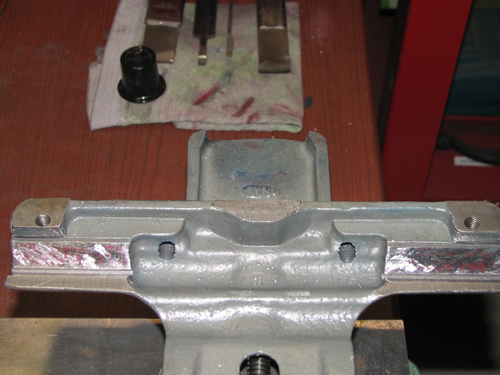
| Measuring the height of the
lathe bed feet before scraping the tops and surface grinding the
bottoms. |
 |
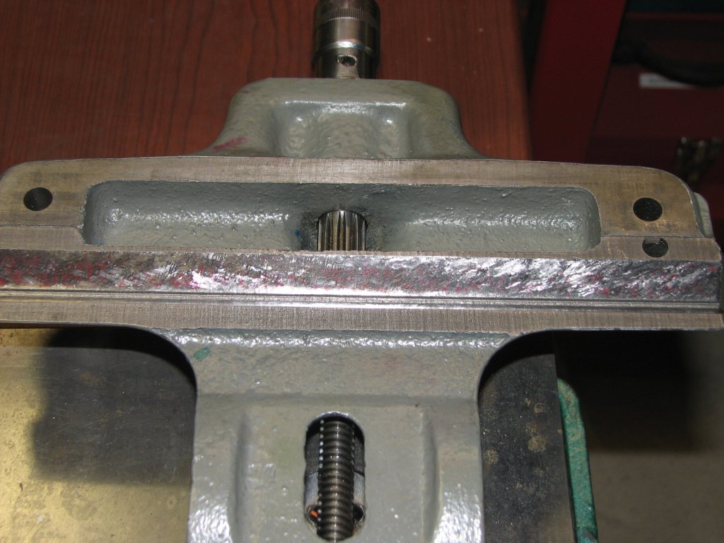
| Scraping where the foot attaches
to the lathe bed. A couple more scraping passes and we'll be ready to
surface grind the bottom of the feet. This should enable
the lathe to sit parallel with the bench top. |
 |
| Rough scraping. Scraping
in
V ways takes a while. |
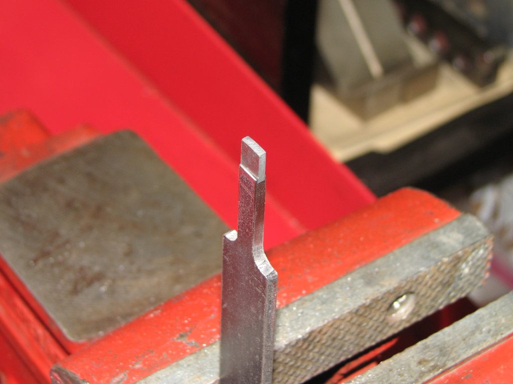 |
| A new scraper is made. The
carbide tip is 1/4" wide and 1/8" thick. Just what I needed. |
 |
| Finish scraping - near side ways. |
 |
| Finish scraping - far side ways. |
 |
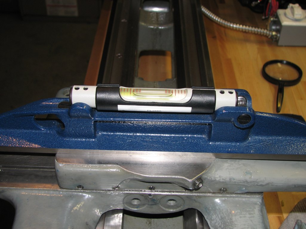
| Leveling the longitudinal axis -
near headstock. |
 |
| Leveling the longitudinal axis - center. |
 |
| Leveling the longitudinal axis -
near tail stock. All three readings are pretty close. |
 |
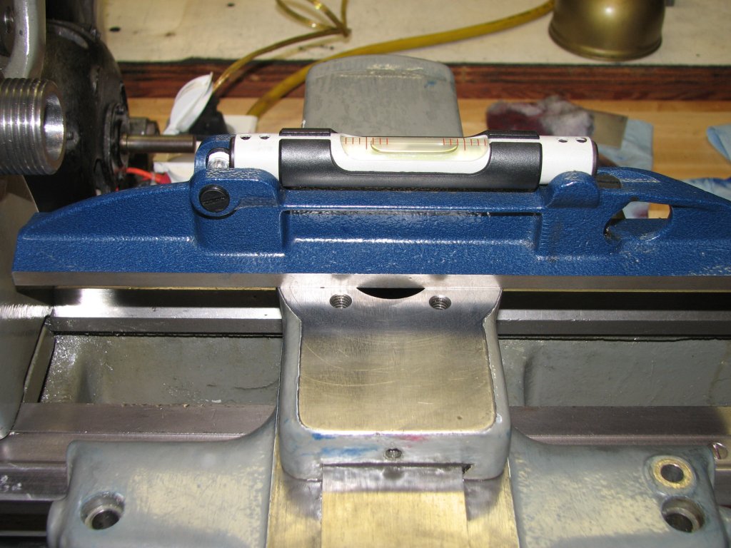
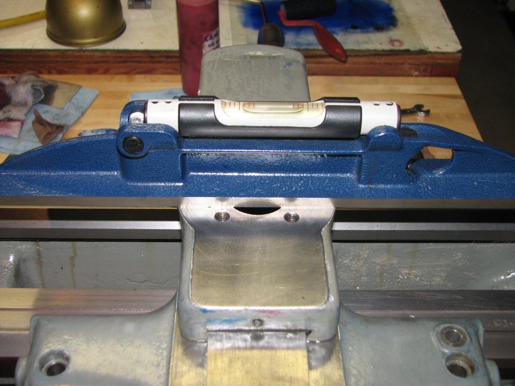
| Leveling across the bed - near
tail stock. |
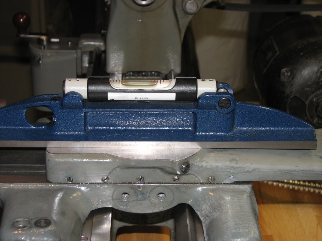 |
| Leveling across the bed - center. |
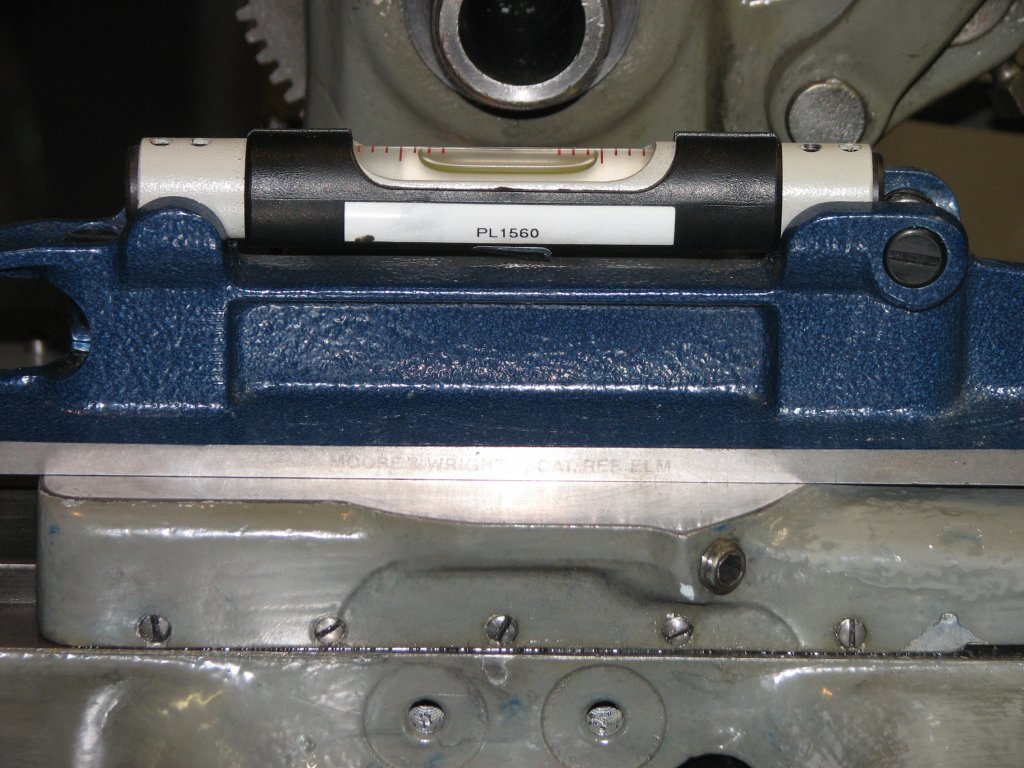 |
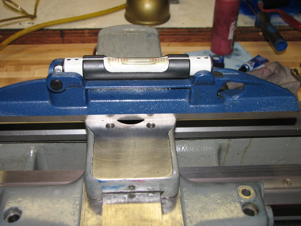
| Leveling across the bed - near
headstock. We have a bit of twist here, but we'll deal with that
by
using Rollie's Dad's Method to remove any bed twist and cutting a test
bar to
check alignment. |
 |
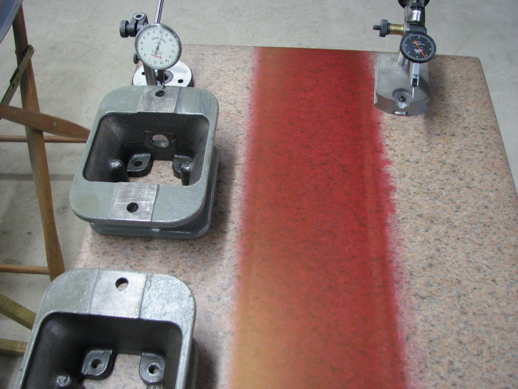
| Not much color showing on the
first print. |
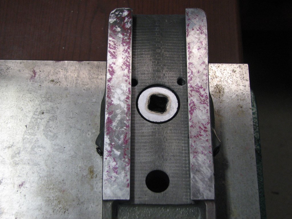 |
| Getting a better pattern here. |
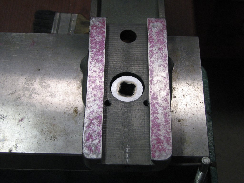 |
| Pretty close to done. |
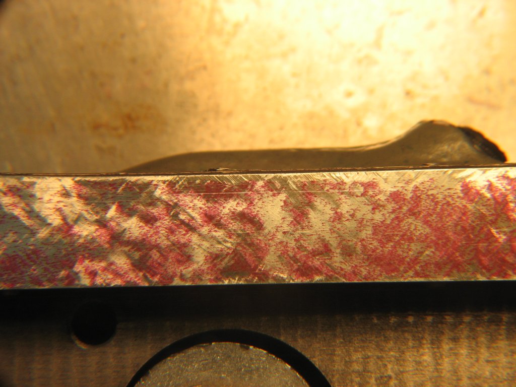 |
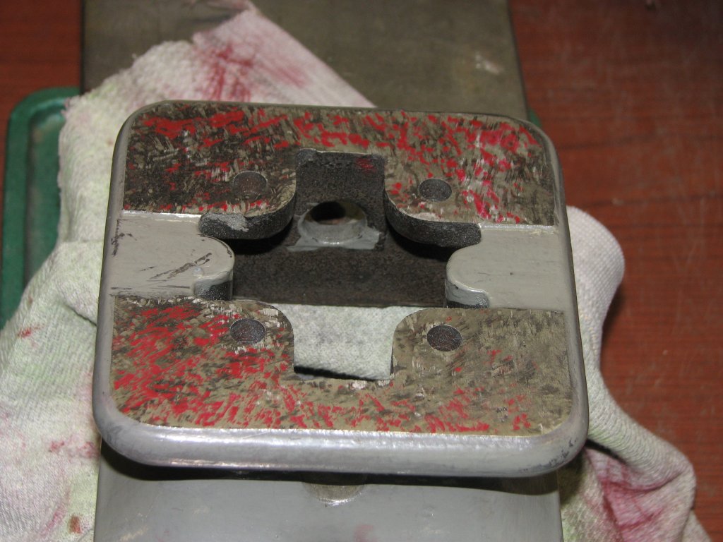
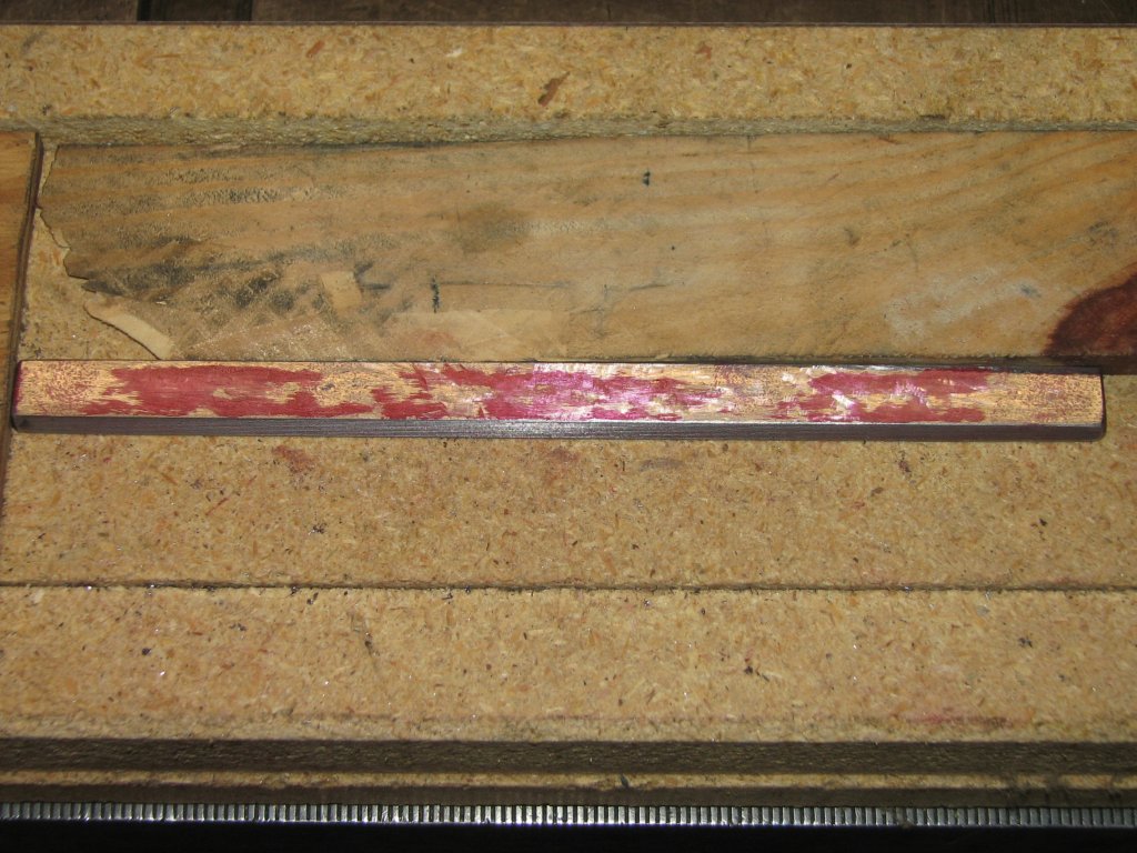
| Close-up of the previous print.
The amount of marking color used on the top surface of the saddle that
I printed from was pretty light, so there's probably half a
ten-thousandth to two tenths between the areas with color and the areas
with no color. There are some unmarked areas that are scraped a
little deeper, but I'm pretty sure that using a thicker coat of marking
compound to print from would probably color pretty much the whole way
surface with red. |
 |
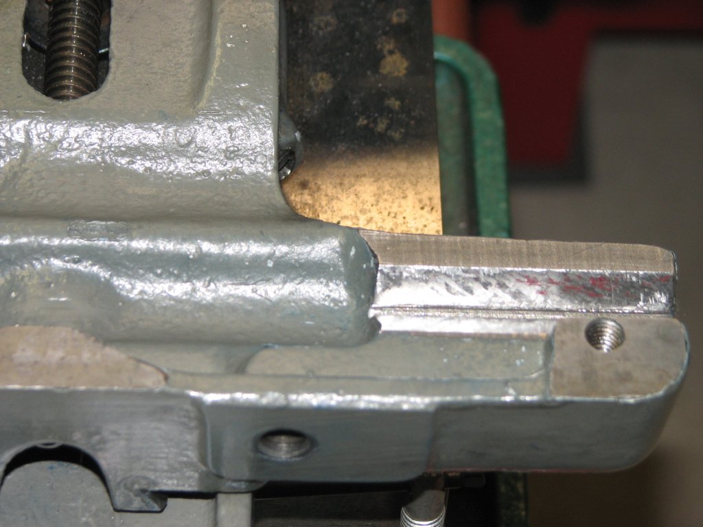
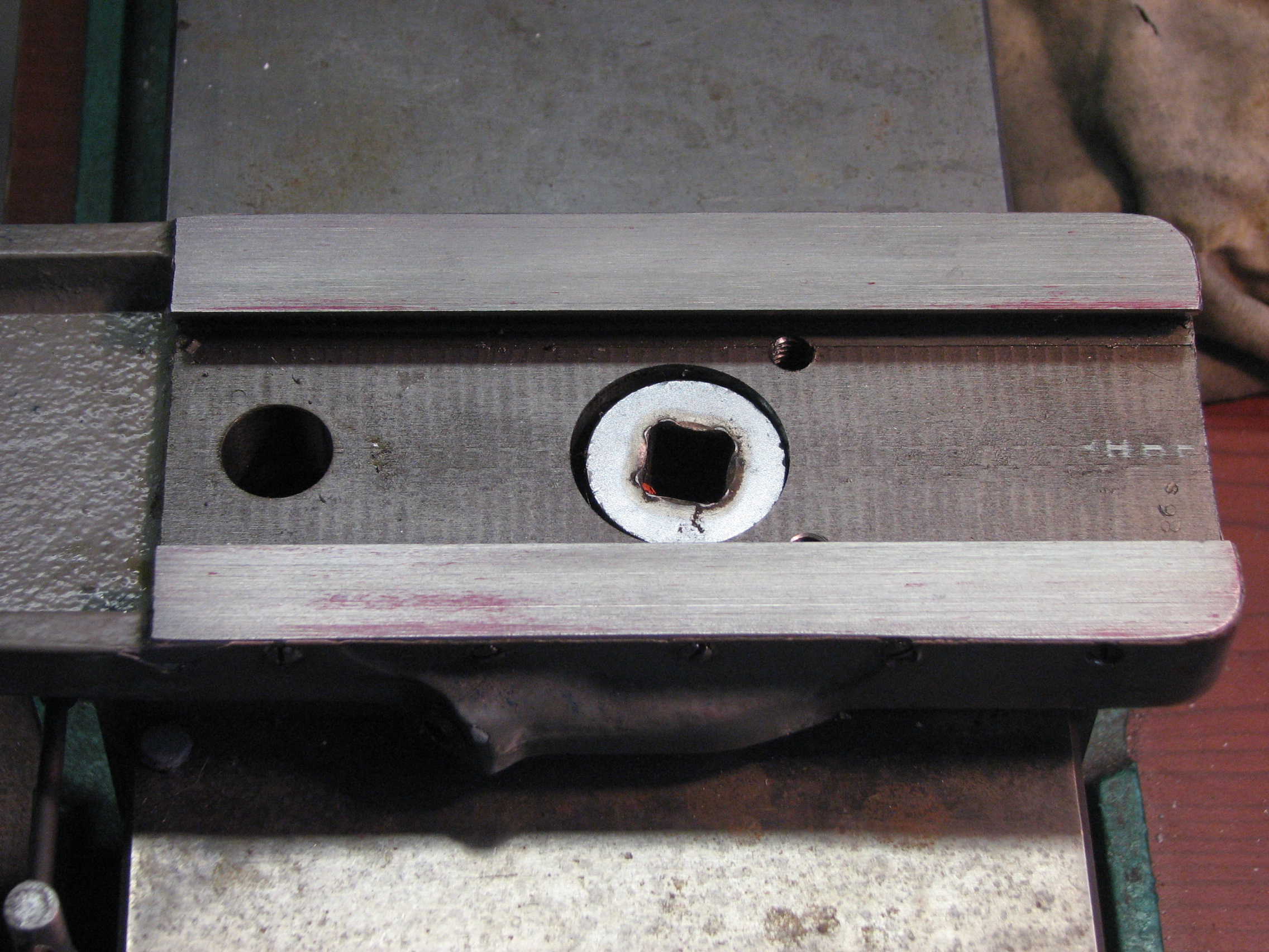
| The cross slide gib was tricky
to print as it is a very spindly piece of metal that bows due to the
being scraped. I used a granite straight edge to push the gib
into the color rolled on to a surface plate. In this shot, I had
another 5 or so passes to go. |
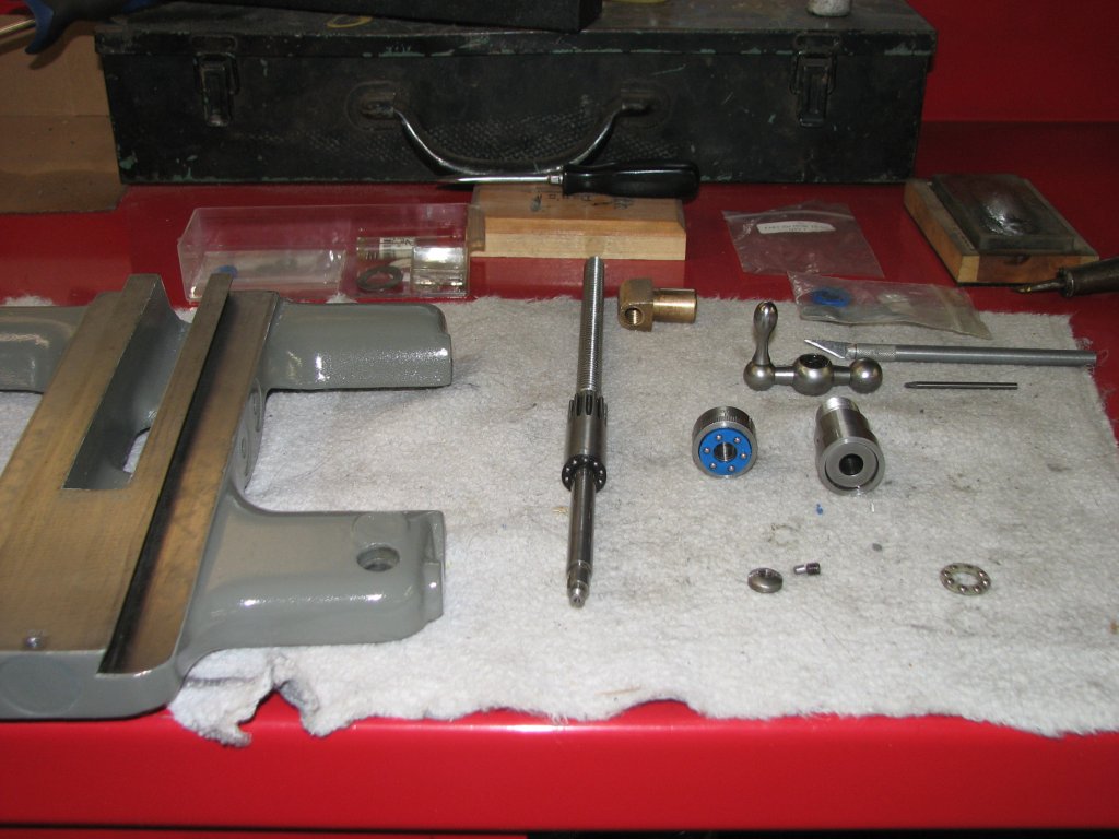 |
| I replaced the cross slide screw
outer thrust bearing. The one on the screw and the one at the
lower right were made from scrap plastic and precision balls. The
new blue one is from McMaster-Carr. After much use, the larger home
made bearing was getting a little notchy due to not using hardened
races. The smaller indside bearing was fine. The new bearing and
hardened races make for a nice feel when turning the crank. |
 |
| All back together and ready to
be aligned |
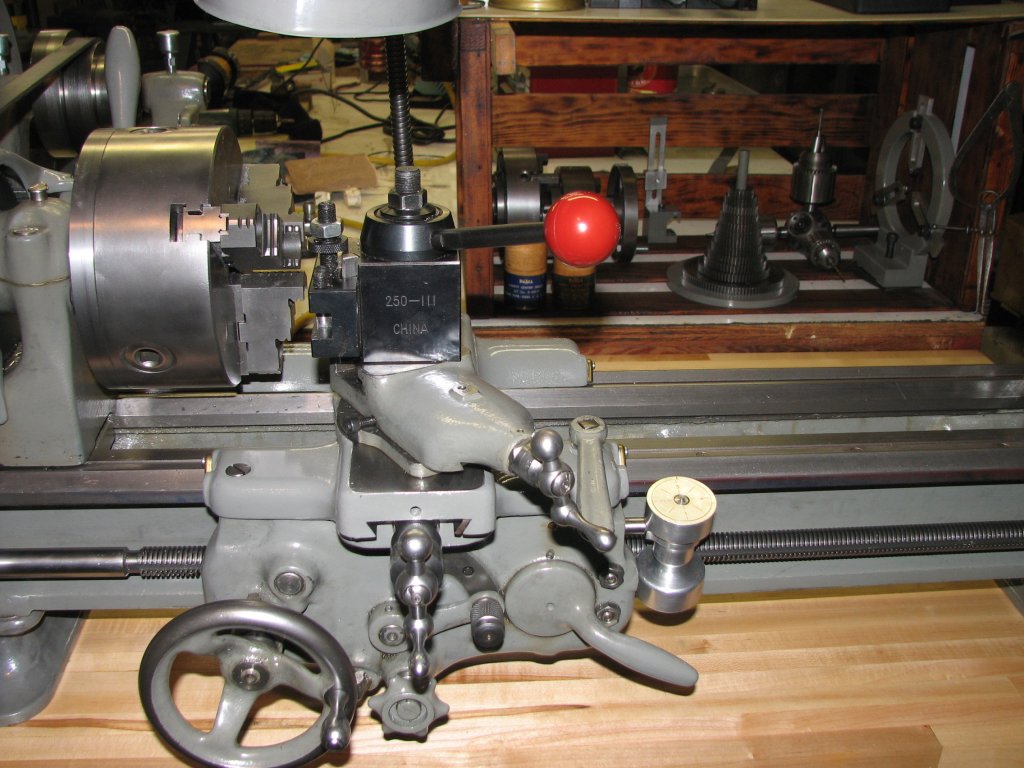 |
| Close-up. While the import
tool holder is of pretty good quality, that big "China" on the front
sure looks tacky. |
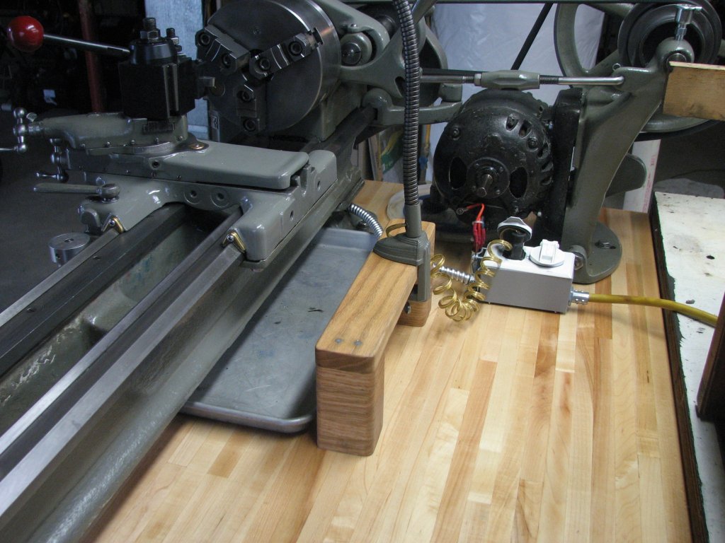 |
| I needed a way to hold the lamp
base and still allow me to position it. Some stacked oak, glued
and pinned with some 1/4" drill rod worked out well. |
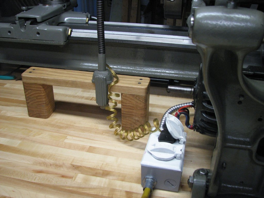 |
| Another shot of the lamp holder. |
© Fager 9-22-11