
|

Grizzly
G3103 Repairs
January 24,
2010 through March 30, 2010
Although I continue
to improve the quality of the mill-work I produce, I got to be
less
and less satisfied with the tolerances I could hold with the Grizzly
G3103 mill. In early January, I finally decided to
attempt to rescrape the mill. I've been working up to this project for
a long time and think I have acquired the tools and the knowledge to be
successful in improving its accuracy.
After spending a
year rescraping the DoAll surface grinder,
I decided that I would afford myself a power scraper. Hopefully
this would speed up the next big job a bit. I purchased a used
Biax 7 ELM
and got familiar with it by scraping a small surface plate and a couple
angle blocks. Using the power scraper is a whole different
process and being able to adjust the stroke length and speed allows you
to change the pattern you leave on the surface you're scraping. I'm
impressed with what I am able to do so far and know that the more time
I spend using the tool, the more comfortable I will become in using
it. I am a bit surprised at how sore I get from using it. I
figured it would be a lot less tiring than hand scraping. That's
only partially true. It still tires the muscles to hold the
scraper so that it makes good contact for hours on end.
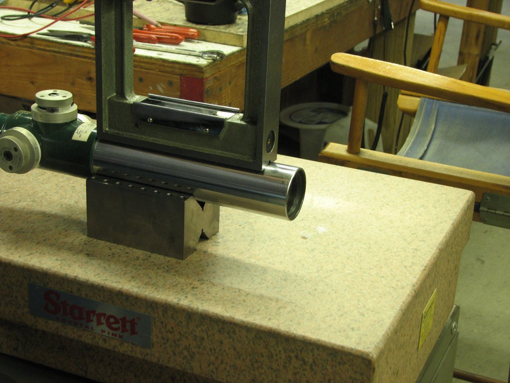
One of the last
items I wanted to have before starting the mill rescraping project was
a cross check level. A
cross check level allows you to view the deviation from flat on two
planes simultaneously. This is a nice tool to have when you're
leveling a machine tool, though I really wanted one to use with my shop
built King-Way style way checking tool. Using the cross check level
with the King-Way tool allows you to see the deviation between the two
ways in both relative height (across the ways) and tilt (along each
way) as you move the tool from one end of the ways to the other.
With a single vial, you can only read one plane or the other for each
pass.
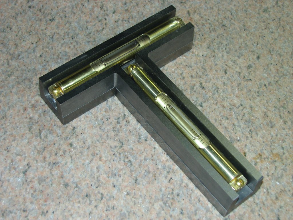
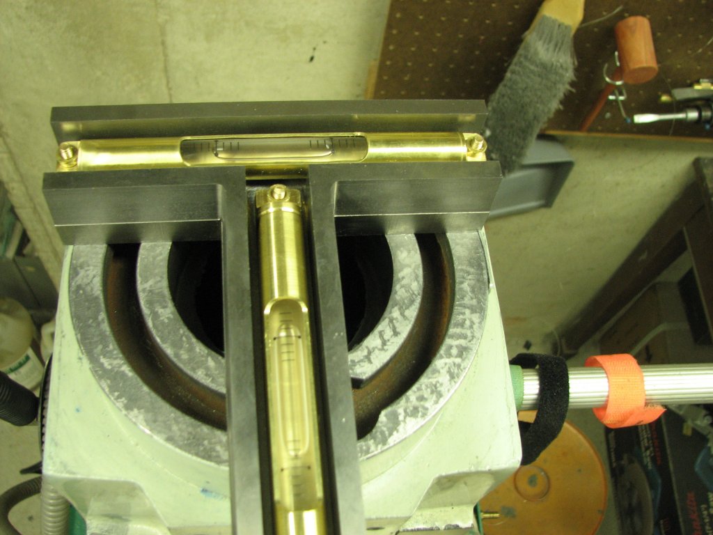
The job of making
the level
was pretty simple. As I had done when I made my 6" precision
level
(for
use where there was limited room), I purchased a couple
level vials that are
replacement parts for the Starrett 199A level. I also bought some
cast (ductile)
iron for the body and brass tube and bar stock for the vial
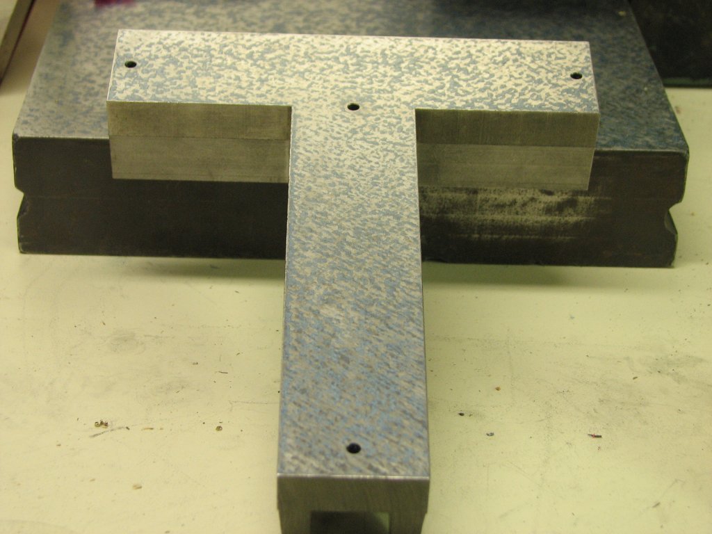
holders. The T shaped body was cut from an eight inch diameter,
two inch thick round. I milled channels for the vial holders,
then spent a week heating and cooling the body to relieve the internal
stress. After a number of heating and cooling cycles, I machined
to top and bottom flat, then heated and cooled the base a couple more
times. After each cycle, I checked for warpage. Finally, I
ran the body through the surface grinder, then scraped the bottom
surface. It took about 10 scraping cycles with the Biax to get
even coverage of bearing points and then another twenty-some cycles
with a hand scraper to bring the count of bearing points up to 30 or
more per square inch. I've checked the flatness over a couple of
months and there is no sign of warping. I still need to build
the adapter to attach it to the lathe tool, but for now it would help
with leveling and scraping the mill.
Now that I had all
of the tools
that I thought I would need for this project, I had no excuse
not to get
started.
 |
 |
| Machined,
ground,
then
scraped
from
a
disk
of
ductile
iron.
Heated
and
cooled
a
few
times
to
help
normalize
the
iron
before
scraping
to
30+
per
inch. |
Two
replacement
vials
from
a
Starrett
199A
give
0.0005"
resolution.
Brass
screws
didn't
work
well
and
were
replaced
by
studs
and
round
brass
nuts |
The first step in
hopefully improving the accuracy of the mill was to measure the mill in
its current state to see how far out of square it was and to give me an
idea of what I needed to accomplish. I started a log book and
began to enter the measurements of the mill. Using my assortment of
levels, straight edges and my K&E autocollimator, I leveled, then
mapped the ways of the mill. This would give me a starting point
for making the mill square.
During the couple
years that I have had this mill, I've complained about the Y axis the
most. With a level on the table and the saddle close to the
column, the level's bubble would show one side of the table high.
When I cranked the saddle out and away from the column, the bubble
would move, showing the other side high. We're only talking about
a few thousandths of an inch, but this was one of the things I
wanted to fix. I haven't heard of any other 6 X 26 mill owners
complain of this, but I don't know how many people have checked for it
either. I came to the early conclusion that the twist I have
found
in every axis (X, Y, and Z) is probably due to the castings not being
aged before and during the machining process. After the ways were
machined, the castings warped and twisted. There's no other
explanation I can think of that would cause my straight edge to touch
on the right rear and front left of a single way. Add to this
that the other way of the same axis shows a similar pattern when
printed with a blued straight edge. So my project is to map out
how much twist I have and try to scrape it out.
 |
 |
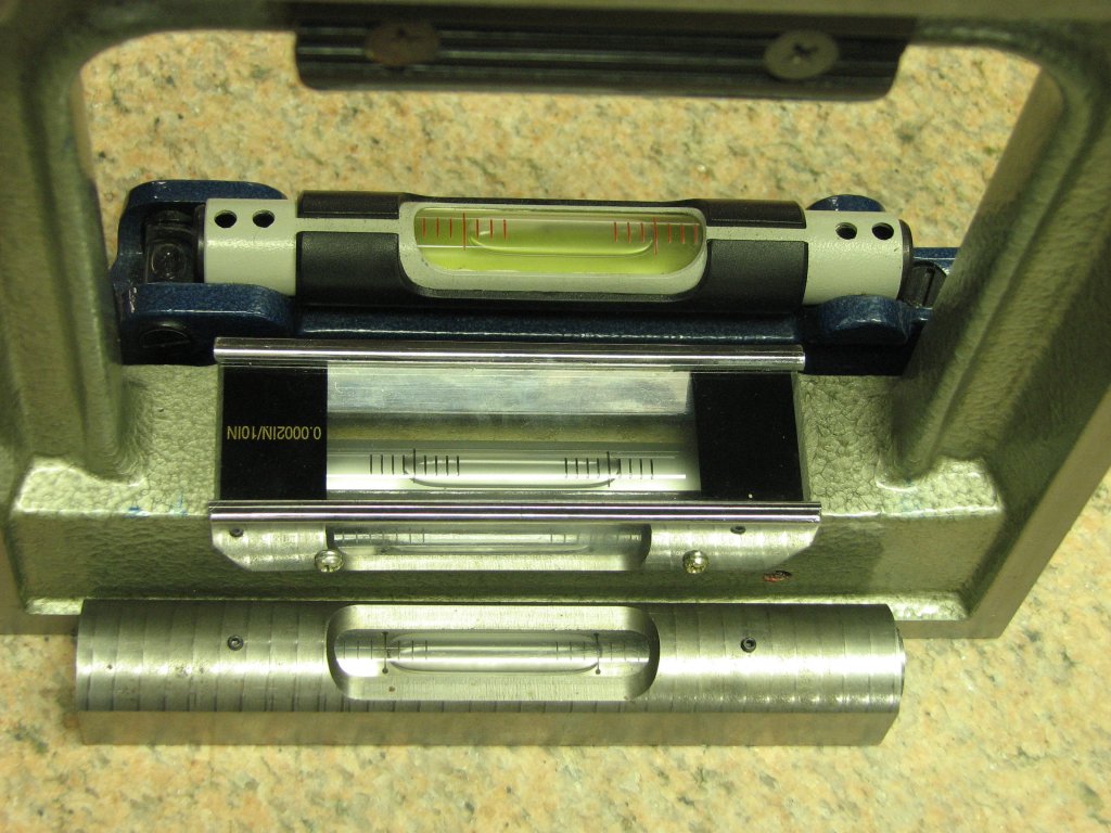
| In
addition
to
the
cross
check
level,
I
have
a
Moore
and
Wright
(rear)
at
0.0035"
per
foot,
an
import
box
level
at
0.0002"
per
10"
and
another
shop
made
level
with
199A vial at 0.0005" per foot. |
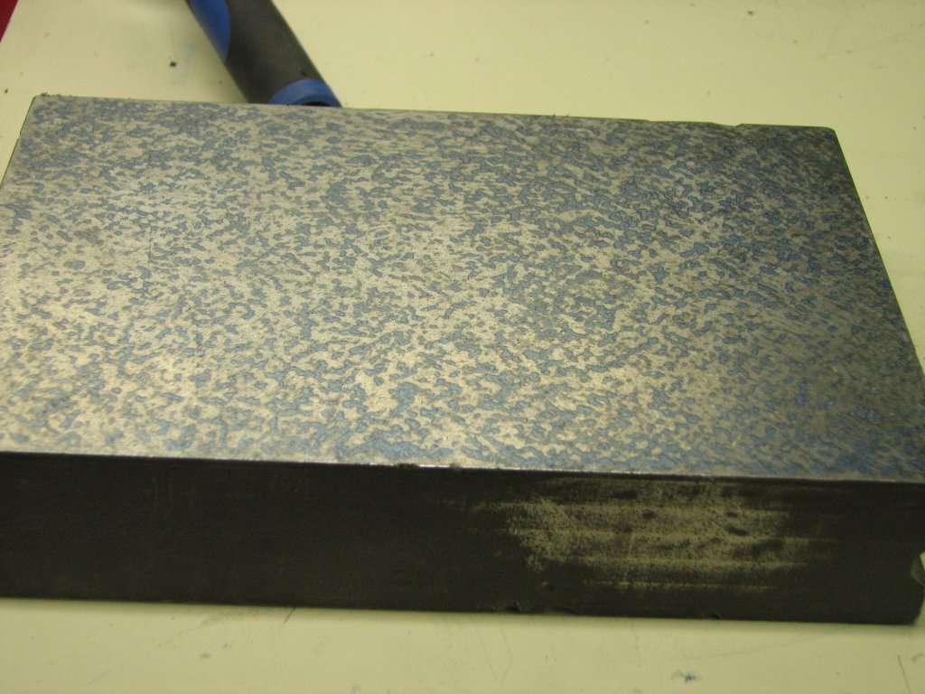
To
test
out
my
"new
to
me"
Biax
7ELM
scraper,
I
scraped
the
back
of
a
cast
iron
lapping
plate.
To
get
over
30
points
per
square
inch,
I
machine
scraped
10
cycles and hand scraped another 25. |
I started my
measuring by leveling the mill using the mill's table as the reference
plane. I then measuring the displacement from level of each of
the ways with the autocollimator. After that, I removed the table and
checked the top saddle ways for level. I then re-leveled and took
another set of measurements. I then removed the saddle and took
my measurements again. Unfortunately, there was a difference in level
between
each way in each axis. This wasn't going to be an easy measuring
or scraping
job.
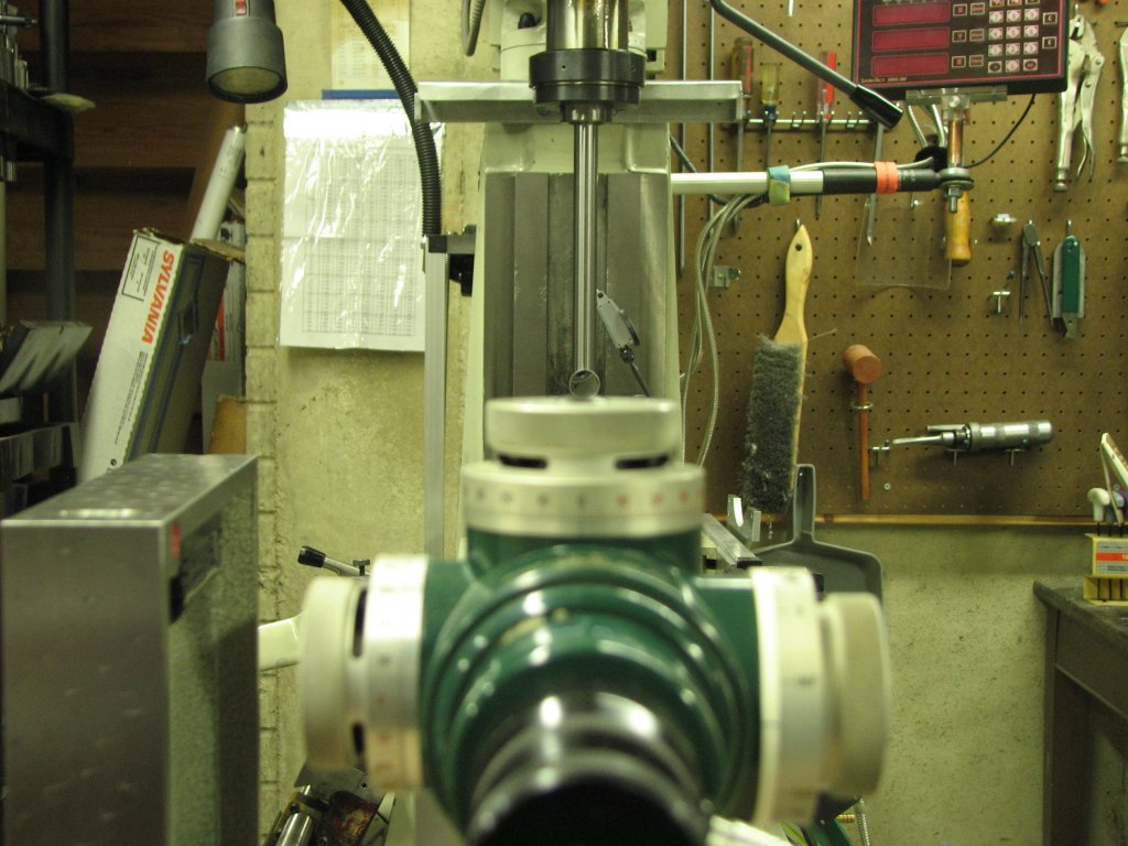
To measure the
spindle plane, I added a 1"
diameter, one foot long precision bar in a 1" end mill holder and put
this
into the R8 spindle taper. Using a quarter wave, front surface
mirror and
my K&E autocollimator, I
checked the alignment of the spindle to that of the Z ways in both the
fore and aft and side to side planes. The closest match was
between the spindle and the right Z way.
These two planes were only out by a couple thousandths over a foot of
distance. The worst alignment I found was measuring the top ways
on the knee where the left
way sloped one direction from the column and the right sloped the
opposite direction. At this early stage, I thought that this was
caused by warpage in both the column
(Z ways) and the knee itself being a bit twisted. I learned later
that this was only partially true.
 |
 |
 |
| The
surface
plate
was
leveled,
then
the
autocollimator
was
checked
for
level |
Shooting
at
a
1"
front
surface
magnetic
mirror
on
a
piece
of
precision
shafting
held
in
a
collet. |
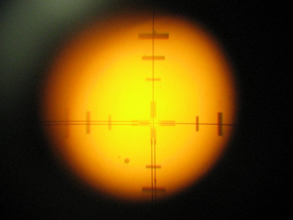
Once
the
crosshairs
were
lined
up
and
readings
taken,
I
compared
the
Z
ways.
Nothing
matched
up. |
Having read
"Machine Tool Reconditioning" by Edward Connelly, I knew that I needed
to designate one surface as the master surface that all other surfaces
would be aligned to. I also knew that I wanted to scrape as
little as possible while still achieving a square machine. Since
the mill had no true 'master surface'
to start with,
I would need to create it. The position of the surface I would
choose needed to be one that allowed me to change the
existing angles of the
mill's ways the least while allowing a precise 90° angle between
the Z ways and the connection (mounting area) that holds the mill's
head assembly..
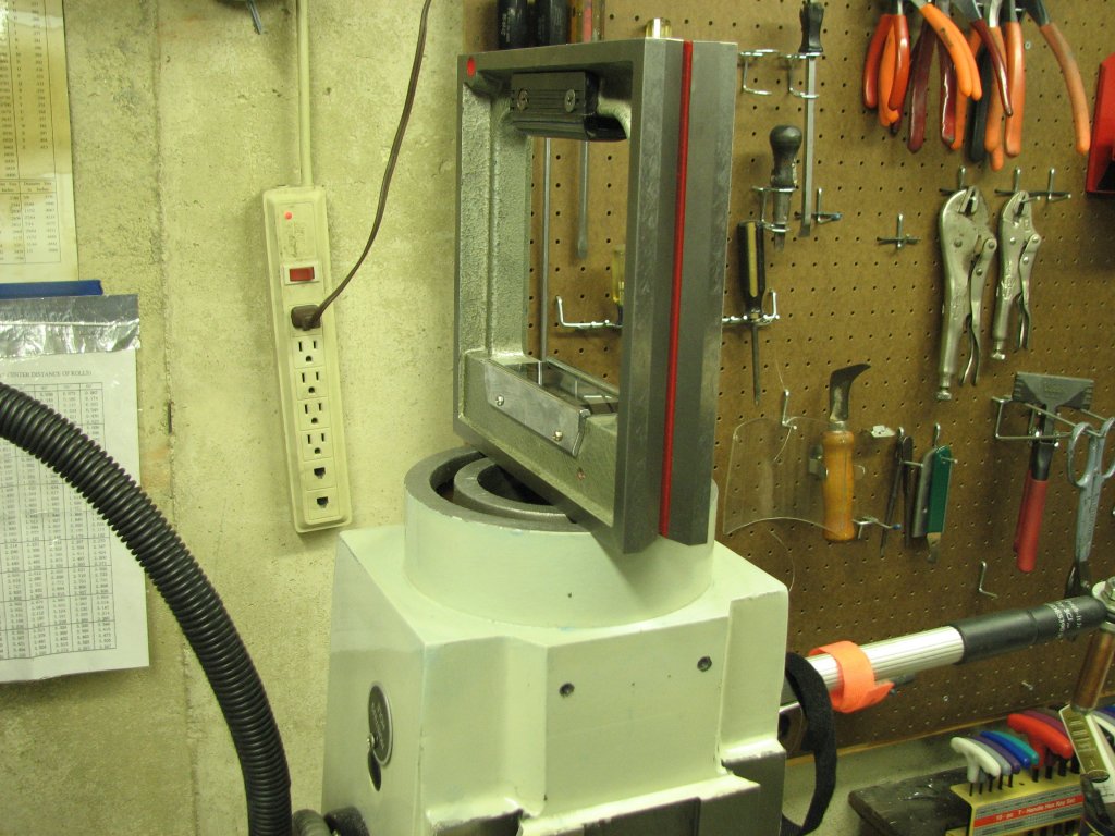
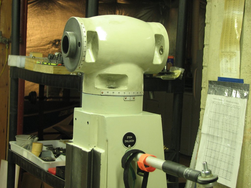
I removed the mill
head from the machine and checked the horizontal
surface that the head swiveled on. Again using both the
autocollimator and levels to double check each surface, I leveled the
mill on its adjustable feet using the horizontal head connector
surface. I
then checked my Z ways for squareness. They were off, but one of
the Z ways was pretty close to square with surface on the top of the
column. I decided that I would start scraping the connector
surface. My goal was to create a plane that was 90° to a plane
somewhere between the current plane of the Z ways that now
sloped in opposite directions. Once I had the Z ways scraped
flat and in a single plane, I would revisit the circular connection on
top of the column and make sure it was as close to 90° from the Z
as possible.
 |
 |
| The
top
of
the
column
showing
how
few
areas
(blue)
made
contact
with
my
small
surface
plate. |
I
used
the
machine
adjusters
to
level
the
column
top
so
that
the
Z
ways
aligned
to
their
best
position. |
Leveling the mill
is not a trivial task when you don't have a single flat axis to work
from. I had to level to a position that was 90° from the
imaginary plane between
the two Z axes. I.E., one way titled toward me by a small amount and
the other way tilted away from me. Trial and error and some
guessing was the only
way to accomplish this. However, I find that in leveling a 4
legged tool, it helps to adjust the leveling feet
diagonally rather than side to side and front to rear. I needed
to end up with the fore and aft inclination of the
Z axis vertical as well as having the left / right inclination
vertical. I ended up with a plane where the difference from 90°
vertical on the two column (Z) ways is about 0.06° in opposite
directions. In other words, one way is 89.04° and the other
is 90.06°.
The above angles
are in the fore to aft position. For the left to right
inclination, I had it a little easier. The small ledge on the
outside of each of the two Z ways were milled pretty close to the same
on either side. Using the box level, then checking my angles with
the autocollimator, I positioned the adjusting feet to make these two
surfaces as close to vertical as I could. I split the difference from
vertical so that I would be removing approximately the same amount of
metal from each way as I scraped.
 |
 |
| Scrape
and
check,
scrape
and
check. Repeat, rinse, and repeat again until it levels. |
Some
period
of
time
later,
we
have
a
scraped
flat
and
level
surface.
A
good
place
to
start
from. |
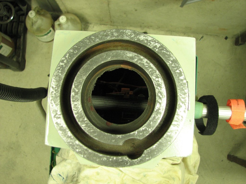
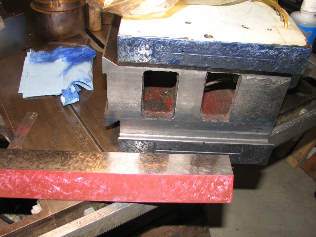
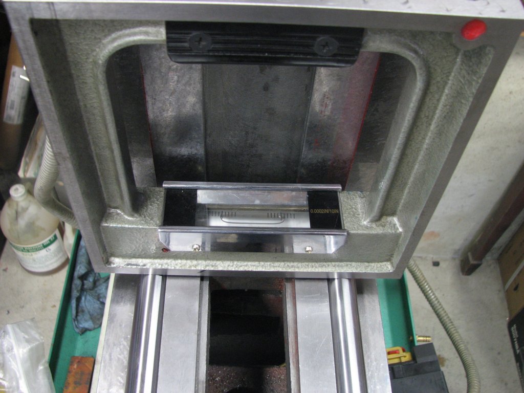
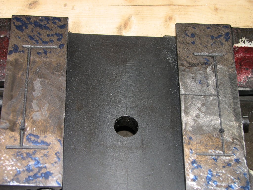
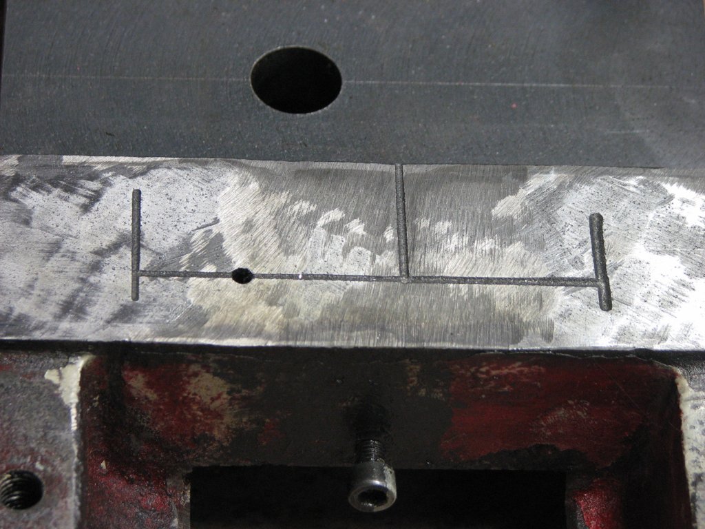
Once the mill was
leveled, I started scraping the two cast iron rings that make up the
mounting area for the head. Between the inner and outer ring is
the tee-slot used to capture the bolts that hold the milling head
assembly to the column. There is a circular enlargement to the tee-slot
in one section to allow the bolts to be removed. As I scraped, I
checked my progress by alternating
between my hand-scraped small cast iron surface plate to
check for flatness and testing with my 0.0002" resolution box level to
keep the surface level in both planes. Before I began scraping, I
used a crosscut file
to quickly remove stock from the front side of the column mount, then
switched to a hand scraper. The factory
surface on this critical connection was pretty rough and my flexible
blade kept catching on the large ruts, so I changed to a heavier, less
flexible blade and powered through the rough areas. This
connection is critical to not only get flat, but also have a large
enough number of bearing points to allow the mill's head to swivel
smoothly. It's important that the head
stays in a single plane as it swivels from left to right so there needs
to be enough bearing points to facilitate a good connection between the
two pieces. None of this was provided by the factory finish.
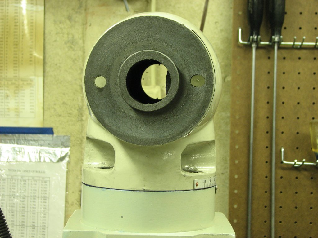
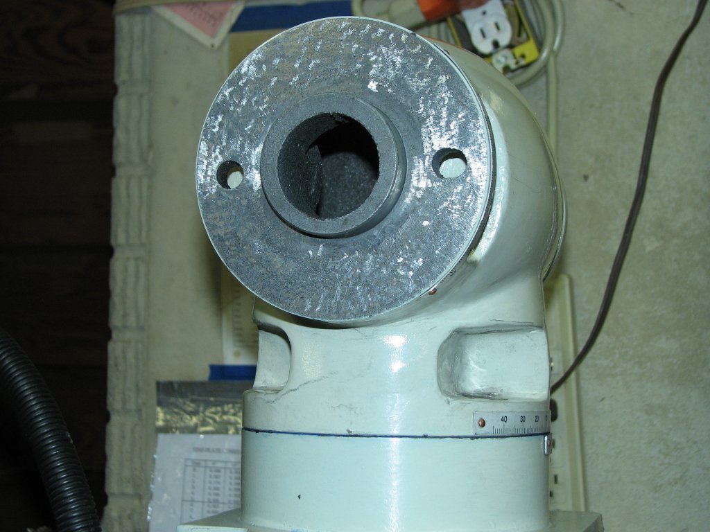
On completion of
the top column mount, I now had my one flat surface to work from.
I decided to move on to the milling head assembly. This assembly
is made up of four sub-assemblies. Just above the column mount is
a "T" shaped connection that allows the head assembly to swivel left
and right. This piece is cast iron and has a flat base on the
bottom with a protruding 3.150" cylinder that fits down into a
similarly sized hole in the column mount. To mount the milling
head in the front and the motor plate to the rear, there are two more
circular flats with protruding cylinders. These circular flat
mounts with cylinders are a bit smaller in diameter than the one on the
bottom and allow both the milling head and motor plate to rotate about
the horizontal axis. Because each of these connections has the
protruding cylinder in the center of a surface that needed to be
scraped flat, it presented a problem. I couldn't just lay the
surface on a flat plate to check flatness without boring a hole in one
of my surface plates. I actually considered this as I have a
couple import 9" X 12" granite plates that are still in their shipping
boxes, but since all three cylinders are different sizes, I'd have to
bore the hole three times to check and scrape all three surfaces.
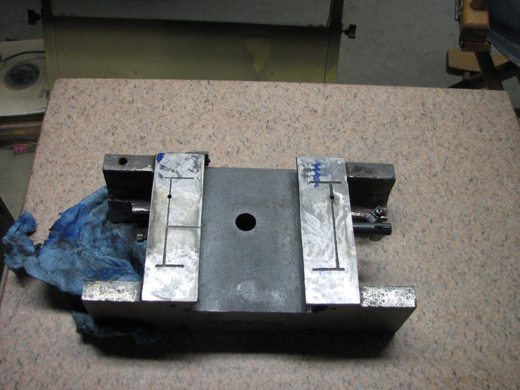
I decided this would be more work that it was worth. Instead, I
used three 3" X 12" granite parallels I had match ground on my surface
grinder. I laid these in a star configuration with the cylinder
from the "T" connection in the center of the three parallels.
While the three parallels didn't quite cover the entire circular flat,
it covered most of it. I covered the three parallels in Prussian
blue and used them as my surface plate with a hole in it. After
each marking and scraping operation, I set the "T" so that the area
that didn't get marked in the previous cycle got marked in this
round. I am not sure how they originally machined the connections
of the T shaped piece. There was a slight
depression around where the cylinder stuck out from the flat portion of
the mounts. I will say that when I set the connector up on my
surface plate and checked the two side surfaces with my master square,
they weren't too far from 90°. No they weren't dead nuts on,
but they were closer than I expected.
 |
 |
 |
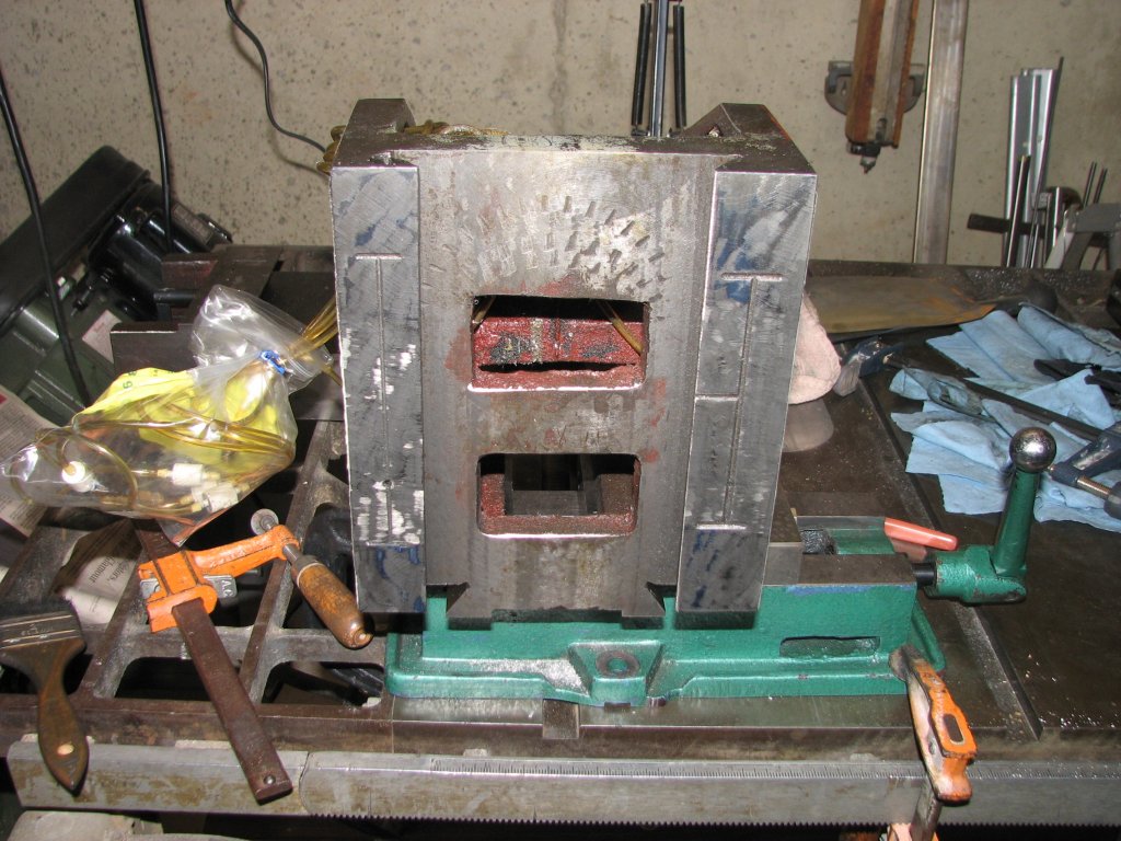
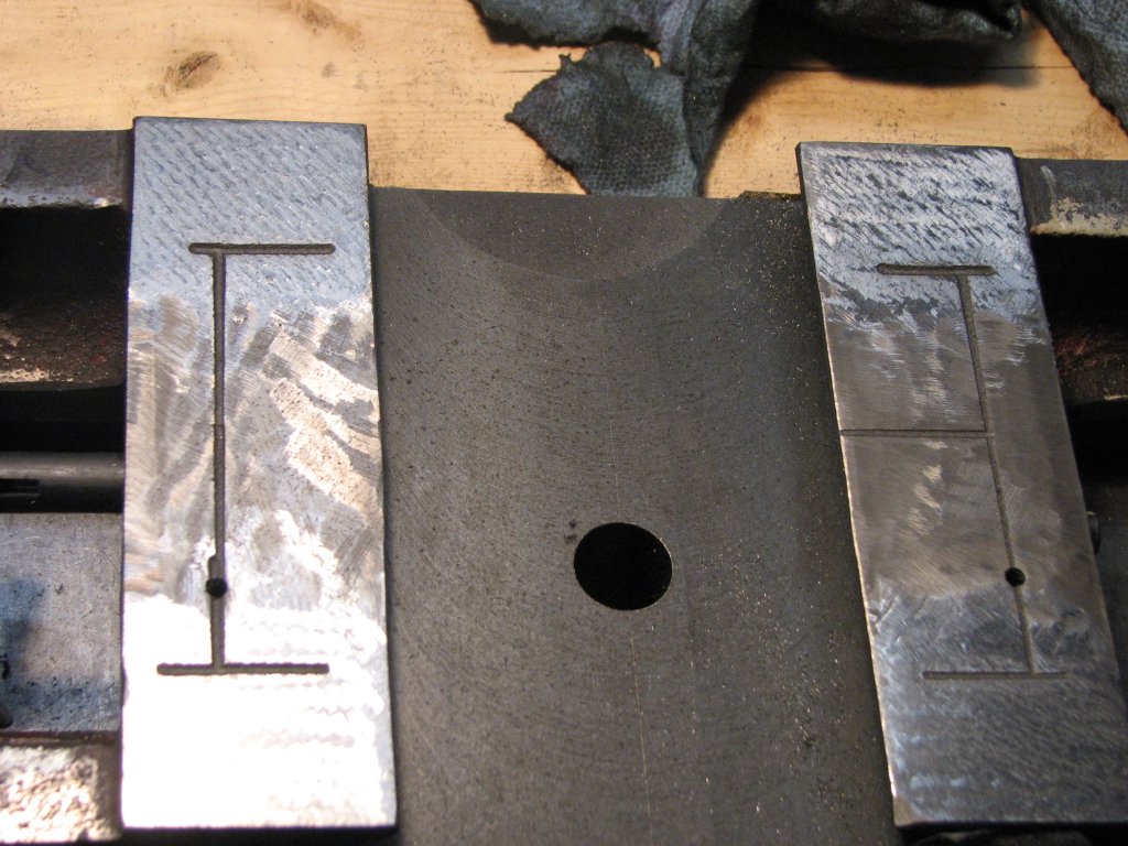
| Test
fitting
the
"T"
that
holds
the
milling
head.
You
can
see
some
evidence
of
Prussian
blue
between
the
"T"
and
the
column
top. |
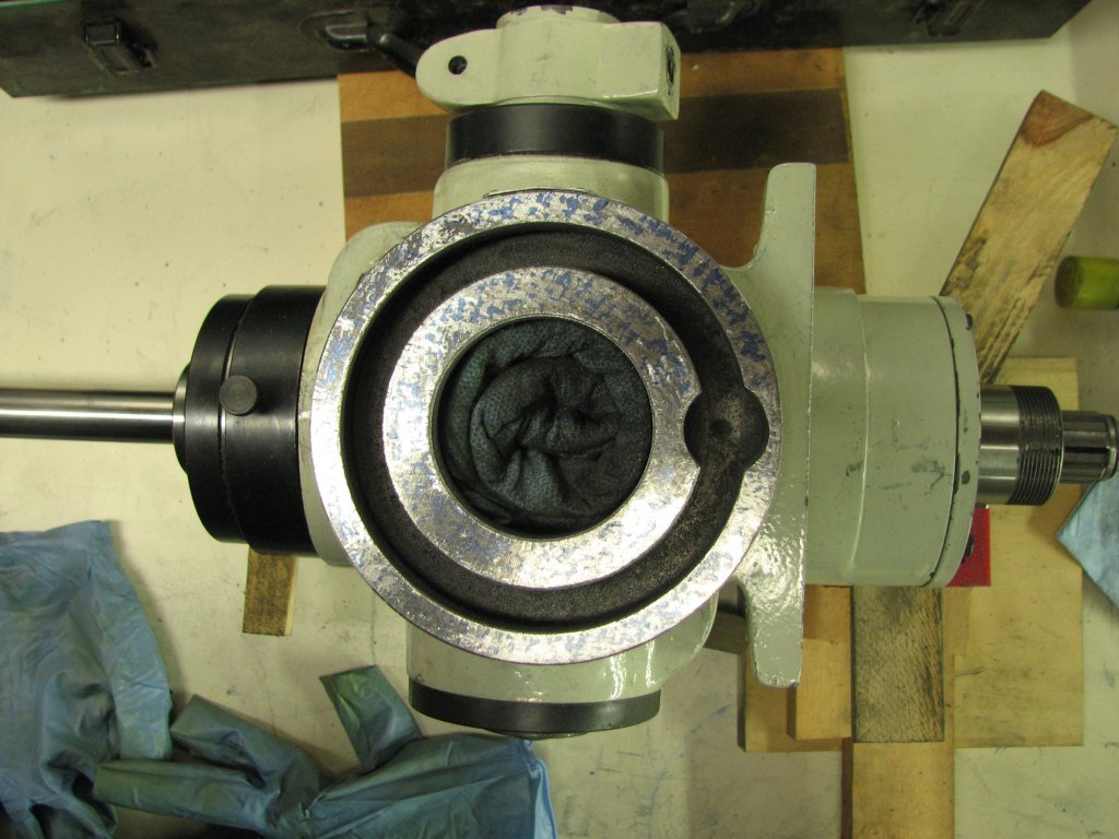
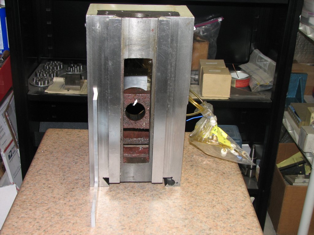
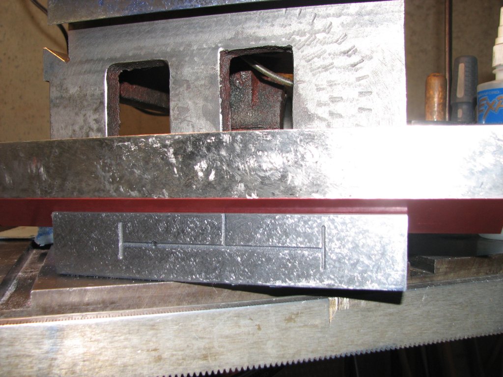
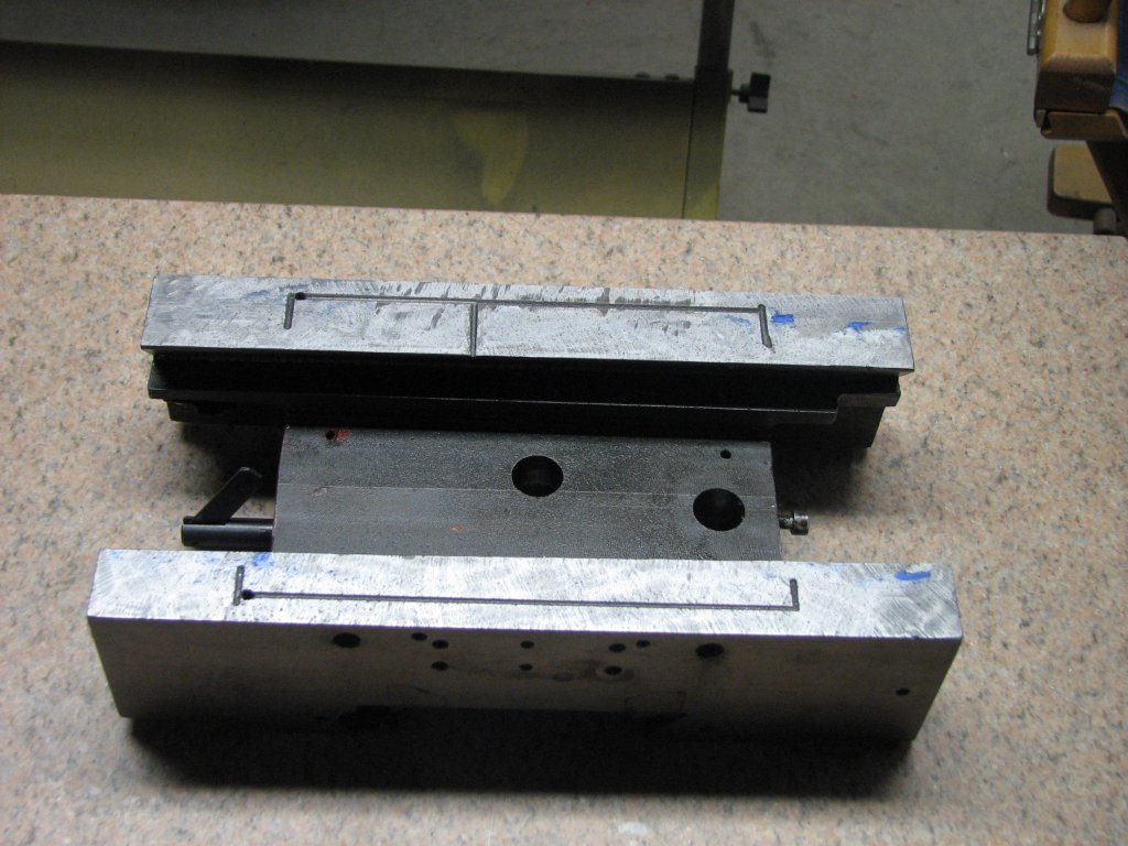
This
is
what
the
surface
looked
like
before
scraping.
Notice
the
slight
depression
between
the
center
cylinder
and
the
two
bolt
holes. |
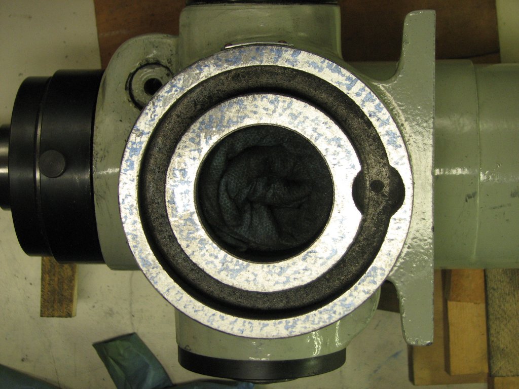
This
face
has
been
scraped
enough
to
make
sure
that
this
surface
is
as
close
to
90°
as
I
can
measure
with
surface
plate
and
Schmidt master angle
plate. |
I scraped the
bottom surface flat, then blued up the top column connection and
checked to make sure I had good contact between the "T" and the column
mount. Once I was satisfied with the contact while the "T" was in
its usual straight ahead position, marked by zero degrees on the scale
attached to the "T" and column, I cleaned the blue from the "T" and
checked other settings. At each increment of 10° in position,
I checked for good contact and also used my box level to make sure that
the surface where the milling head attached remained level.
With all three of the "T" connections scraped, I still had two surfaces left to deal with on the head assembly. The motor mounting plate and the milling head. There wasn't a lot to do on the motor plate as it is not critical if the motor is not aligned to seconds of arc. I scraped it to good bearing and made sure that it stayed close to level as I rotated the plate through its range of possible positions. Setting up the milling head was a different story. My goal in working on this mill was to improve its accuracy. Getting the head to be dead on 90° to the table meant that this connection, as well as the column to "T" and the column to Z ways had to be as perfect as I could accomplish. In order to scrape the proper angle into the mill head connection, I needed to find the center line of the R8 internal taper in the spindle.
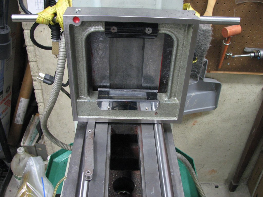
First, I removed
the belt guard cap screws, then removed the spindle
pulley. The milling head can then be removed from the
guard. I inspected the taper and went over it with a slip stone
to make sure there were no burrs. I had purchased some new ETM
brand end mill holders that checked out to be pretty concentric and
mounted
some precision shafting in place of an end mill. This would, in
theory, extend the center line of the R-8 taper out to where I could
check it
against the mounting flange on the surface plate.
 |
 |
 |
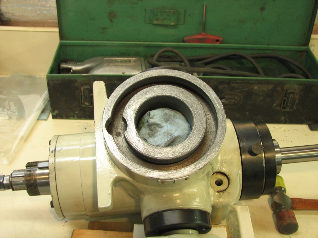
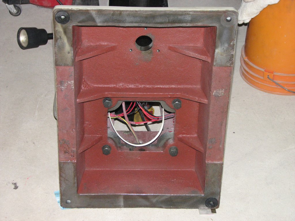
| The
milling
head
has
been
removed
and
had
a
towel
stuffed
into
the
center
hole to prevent chips from getting into the spindle bearings. A
7/8" |
precision
shaft
in
a
collet
allowed
the
tilt
of
the
head
connection
to
be
measured when the connection was placed on a surface plate. |
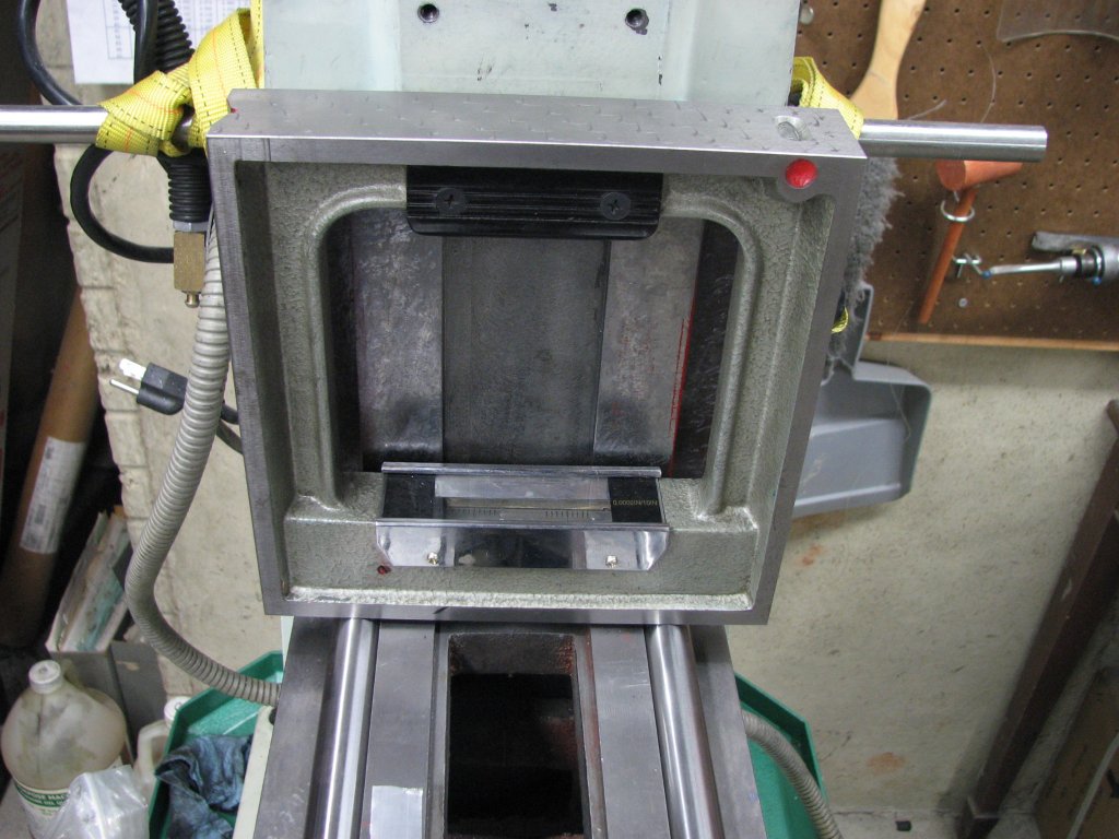
The
connection
was
scraped
until
the
distance
between
the
surface
plate
and
shaft
remained
constant over the length of the shaft. |
It worked pretty
well. I first set up with my new 3/8" end mill holder and a piece
of 3/8" drill rod about a foot in length. I cleaned up the flange
a bit with a hand scraper as there was some ragged edges near the
bottom edge of the flange. I cleaned and polished my Starrett
surface plate and carefully laid the head, flange down, on the
plate. I then used a 'half-tenths' indicator to check for
parallel along the drill rod. This would show me the relationship
between the R-8 taper and the head's mounting flange. As I
measured from end to end of the drill rod, I also rechecked with the
spindle turned in quarter turn increments. The end of the drill
rod was low by 0.012" at the best and 0.016" at the worst compared to
the section of drill rod just outside the end mill holder. That's
a lot. I was also showing 0.004" run out at about 12 inches from
the end mill holder.
There was only 0.0005" run out just outside the end mill holder.
I swapped a 7/8"
collet for the end mill holder and used a 12" piece of 7/8" precision
shafting. I got almost identical results. This told me that
there was a slope of about 0.001" per inch on the head mounting
flange. Since the flange has a diameter of about 5 inches, that
meant that I needed to remove about 0.005" from the top of the flange
and nothing from the bottom. It took about 15 cycles of
measuring, marking and scraping to get the flange parallel to the
precision shaft. It took another 15 to 20 cycles to get a nice bearing
surface on the circular area.
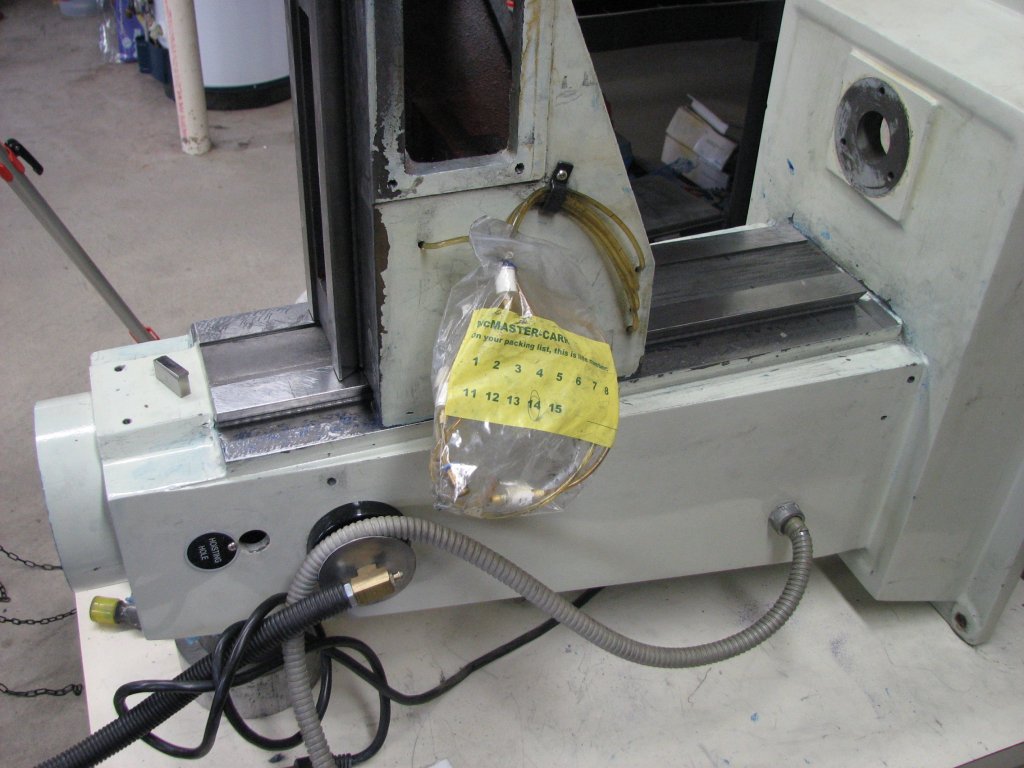 |
 |
| One
of
the
many
tests
between
the
knee
and
column.
The
bag
helped
keep
the
disconnected
lines
filled
with
way
lube
from
getting
everywhere. |
A
shot
of
the
mill
that
few
people
get
to
see.
I
set
the
4
connection
fasteners
to
75
foot
pounds
to
make sure they were good and snug. |
Once I was
satisfied with the surface of the milling head and head connection, it
was time to lay
the mill on it's back. I had considered scraping the Z ways with
the mill in a
vertical position, but this would make checking the plane of each way
much more difficult. It would be easier to lay a level on a
horizontal surface than to hold a box level to a vertical surface. In
order to
position the mill on its back, I would need to
support it so the Z ways would be held in an exact horizontal
plane. Again, the mill needed to be horizontal in both the front
to rear and side to side planes. As it turned out, I had a couple of 4"
cylindrical pieces of steel that were very close to the right height to
prop up the end with the head connection. I leveled the Z ways
length-wise, then shimmed each corner to get the side to side plane
level.
 |
 |
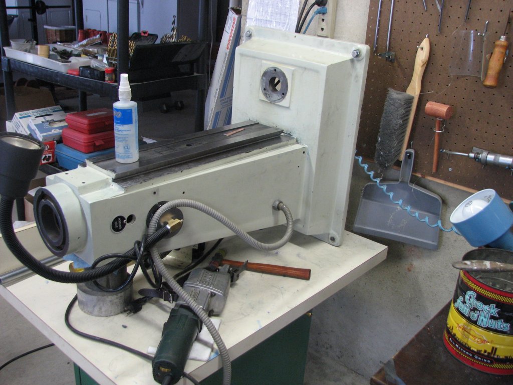
| The
mill's
base
and
column
have
been
laid
on
their
back
and
supported so
that the Z axis was level in both fore and aft and side to side planes. |
With
the
Z
ways
now
horizontal,
I
started
with
one
way
high
toward the
camera and one high at the opposite end. By this shot, they are almost
level. |
With the box level
measuring the head connection plane, now vertical instead of
horizontal, I made sure that the plane was parallel to the force of
gravity. I then mapped out the Z ways using the box level. The left way
was sloped up at the base end and a couple thousandths low in the
center and at the head connection end it was higher than the center,
but lower than the base end. The right flat way was sloped up at
each end and low in the center, though, as with the left, it was higher
on the base end than the head end. Each of the two ways were
about 22" long and 2" wide, so I could use one of the granite angle
straight edges that I had made as a scraping master. Because my
goal was to make the ways perpendicular to the head connection, as well
as flat in both the length and width, I started out printing each way
from the Prussian blue coated granite master and guessing at how much
material to remove to achieve all my goals. Because it was
necessary that the two ways were in the same plane, I
would need some sort of jig to keep the ways the same height and even
with each other. It could be done with a couple of parallels to
lift the box level over the raised area between the ways, but using
the parallels introduces more room for error as there are more pieces
to deal with. However, if I scraped the knee Z ways flat using my
surface plate, I could use the knee as a template. Between the
two setups I would be able to scrape the plane of the Z ways pretty
close to true.
 |
 |
| Though
the
surface
the
indicator
base
sits
on
does
not
support
or
guide
the
knee,
it
is
easily
scraped
flat
and
square with a surface plate. |
Once
flat
and
square,
it
makes
for
another
way
to
ensure
that
the
obstructed
Z
ways
are
flat,
true
and
at
the same height. They also look sharp. |
I blued the master,
printed both Z column ways and scraped about 12 cycles before I started
getting
sore from working on the concrete floor. Working on ways about 8"
off the floor wasn't going to allow me to produce the best
finish.
I solved the issue by placing an old Formica counter on top of the
mill's base, then hoisting the mill column casting to rest on it.
I used the
same steel cylinders to block up the connection end and shim stock to
level the base. The ways were now about 30" from the floor.
Still a bit too low for my liking, but a whole lot better than working
on the floor. I had switched to the Biax 7ELM scraper after about
the third round of scraping - just enough time to figure out where the
problem areas of the ways were.
As it turned out,
near the vertex of the dovetail ways, on the wide flat way, there was
an
edge that stuck up higher than the rest of the ways. This was
caused by the ways of the knee not contacting that section of the way
as the knee was moved
up and down the column. Because it was close to the vertex,
this area was
not able to be scraped easily with the power scraper without the chance
of
putting dings or gashes in the angled way. To scrape this area I
switched to a 1/16" thick carbide bladed hand scraper that had been
further thinned by a couple years of sharpening the sides of the blade
with diamond
paste. A couple cycles of scraping had the edge knocked down to
the level of the rest of the way. By about cycle 16, I was
starting to get points in the mid-section of the ways. I was
still high on the base end, but it was coming down cycle by
cycle. I had stopped scraping the very end by the head connection
side of the ways once I had about a two inch section of the end of the
ways that were flat and showed points all across the width of each
way. Leaving this end unscraped would effectively lower the
opposite end and bring the way into being perpendicular with the head
connection.
After I had bearing
points showing along the entire surface of each of the flat Z ways, it
was time to make sure that the ways were in the same plane. As I
said before, I would accomplish this by using the knee as my
template. However, first I needed to check the ways that
contacted the column on the knee. Back to the surface plate. The
knee was as bad as everything else I had checked. With the ways that
contact the Z ways of the column sitting on the surface plate, I used a
"L" square to check to see if the Y facing ways were at a 90° angle
to the plate. They were close, but one was about 91° and the other
was 89°. More twist. I then checked what amounts to the
height of the Y ways by placing a piece of 1/2" drill rod in the vertex
of the flat and angled ways. and using the "L" square to see if it was
perpendicular to the surface plate. This measurement was way out.
(I knew this from using the mill.) The knee leaned to the right.
To visualize which plane this is; you're above the mill looking down on
it. The connection for the head assembly is in the center of an
analog clock face. 12 o'clock is behind the back of the column
and the mill's table runs from 9 o'clock to 3 o'clock. The knee would
normally extend toward 6 o'clock, but in this case, the Y axis points
to between 6 and 7. It faced to the left of 6 o'clock by
an
amount equal to 0.0045" over 6". To make the knee point at a
right angle, I would need to remove metal from the knee's right Z
way. Since the crank end of the knee was not only facing a bit
left, but also a couple thousandths lower than the column side of the
knee, I
would need to correct the Z ways on the knee in two planes.
Fortunately this isn't
as hard to do as it is to describe.
 |
 |
| With
the
first
print
of
the
knee's
Z
ways,
we
find
that
there
are
only
small
contact
patches
in
each end of the ways. Not too good for rigidity. |
Checking
for
squareness
of
the
tops
of
the
knee's
Y
ways.
In
this
check,
the
top
of
the
L
square should touch. Instead, the bottom does. |
I made a jig to
hold the knee with its Z ways facing up and clamped it to my cast iron
saw table. Out came the tools and I ground, filed and scraped for
two evenings to remove enough metal to make the knee sit on it's Z ways
and be close to perpendicular to the table in all directions. Or close
enough
for now. All I really needed at this point was for the knee to be
perpendicular to the surface plate and for there to be enough bearing
points that I could use it to check the plane of the Z ways on the
column. Removing about 4 thousandths from a way - even a short
one like the Z on the knee is a lot of metal when scraping. I
didn't even try. I started with a belt sander and some 60 grit,
progressed to a bastard file, then the Biax, and finally hand scraped a
couple cycles. In between every few cycles of each tool, I
cleaned up the knee with a shop vacuum and alcohol wetted towels and
put it back on the surface plate. I didn't want to remove too
much material. Once that the mill is back with the column in the
vertical position, I will add the gib and check the Y knee ways for
level and being parallel. Eventually the crank end of the knee will be
a small amount higher than the column side. This will allow the
knee to take the weight of items on the table and the forces subjected
to the knee in machining without sagging. The specs I've heard
amount to about a half thousandth high at the crank end.
When the knee was
square, I blued its Z ways, then lifted it on to the column which was
still lying on its back. I slid it along the ways; from the head
end to the base end and looked at the pattern it left on the column's Z
ways. Amazingly, the pattern was very close to the same pattern I
saw when I printed each way separately with the granite master.
If I had seen markings on both outside edges of the ways, or both
insides, or one of each, I would have had to adjust the column ways to
bring the two of them into a single plane. As it was, I could
continue my scraping on the column Z ways, confident that the ways were
flat with each other.
I did encounter one
issue with the knee to column fit. I had removed enough material
that the vertex of the non-gib side of the knee was touching the
machined groove that is cut in the vertex of the column Z way.
There are three choices here that I can think of. Add a piece of
Turcite B to the angled
way of the knee ways to build them up, or cut the tip of the vertex of
the knee ways down, or deepen the channel at the vertex of the column's
non-gib side flat and angled Z way. As I looked at the position
of the knee on the column, I saw that the knee was closer to the
gibless side of the ways, than to the gibbed side. I could deepen
the channel of the right column Z way and shorten the vertex of the
knee ways without running out of width on the gib side of the column's
Z ways. I had read about this happening in Connelly's book and
knew that it was a real possibility because of the amount of metal I
needed to remove to straighten out the knee, but having the knee square
with the column was more important than having the ways shifted a bit
to the left.
 |
 |
| My
hand
scraped
55°
angled
template
has
been
"blued"
with
red
marking
fluid. I'm ready to print the non-gibbed side of the angled knee Z way. |
The
template
is
in
place
and
is
transferring
color
to
the
way. Using two
templates, I can ensure that the way will be at the right angle as well
as flat. |
By the beginning of
March, I was getting close to having the Z ways finished. I was
now able to measure the Z on the column with my 2 ten-thousandths
sensitivity box level and the bubble never traveled further than 4
lines. Eight ten-thousandths difference between the lowest and highest
spots on the ways. The scraping goes a lot slower at this stage
since there are many bearing points to scrape off in each cycle.
Also adding to the lack of speed is that the straight edge needs to be
spotless before you can add the Prussian blue and make a print on the
ways. If you pick up a fleck of metal in the blue, you won't get a true
print or maybe no print at all.
I was also checking
the column Z ways by bluing the knee and setting it in position, then
sliding it along the column. I had my box level on the crank end of the
knee and in addition to watching the bubble in the level, I watched the
markings left on the column ways. In the early scraping cycles,
the bubble moved from the left, to the right as I traversed the ways.
It moved much less now, but I still had about a half ten-thousandth to
go. I had decided I would stop when I could keep the bubble
within 1 line to either side of the box level and I had full coverage
of bearing points. This would be about a half of a graduation on the
Starrett vial. Trying to chase after no movement of the level bubble
was
not something I was planning on doing - even if it was possible.
With 2 ten-thousandths per 10 inches sensitivity on the box level,
almost everything I did changed the bubble position. Whether I
touched the level with a warm finger, breathed on it, didn't position
it in the exact same spot, you name it and the bubble moved. I
had already improved the Z ways to be much more accurate than they were
when the mill arrived a few years ago. The knee now moves with the
touch of
a finger, rather than a stiff push, so I know it is going to be a great
improvement. My biggest question is whether the mill has finally
settled in and if I can expect the new accuracy to last. I tend
to think that if the casting does continue to settle in, it will do so
to a much lesser degree than it has done up to this point. I am
hoping so, anyway. I have a whole lot of time invested in this mill now
and I'd hate to think that it would twist like a pretzel after all the
scraping I've done.
 |
 |
 |
| With
a
0.012"
feeler
gage
under
the
left
side,
the
level
bubble is
centered. Scraping the bottom right angled knee Z way, the left
side will rise. |
A
day
later,
the
feeler
gage
has
now
been
removed
and
we have 5 increment
lines to go before the knee will level out. |
By
the
end
of
the
next
day,
we're
showing
within
a
ten-thousandth of
having the knee level. Getting the knee level here will allow the
table to be level. |
March 13, 2010
This afternoon I figured I'd scraped the column enough. With the
box level set up on 2 pieces of 7/8" diameter shafting, I could move
the level
from the base to the top and the most the bubble moved was less than 1
division. I'd been at this point for 2 days and the only thing I
was accomplishing by scraping was more bearing points. Not to say
this is bad, because it isn't. It's just that this is about as
good as I am going to get it without driving myself into boredom.
I'm ready to move to the next axis.
Using my engine
hoist, I lifted the base and column assembly and while it hung in the
air, I checked and cleaned the base and mounting points. I set it
on the stand and bolted it down, being careful to torque the bolts
incrementally and to about 75 foot pounds. I then leveled the
column using the box level on the Z ways. The difference between
trying to level it before and after scraping the ways was drastic. One
half hour later and I was close to dead level. The connection for the
head
was right on level in the front to back plane and about 1/2 thousandth
high on the left. This was due to having to make an adjustment to
the left Z was dovetail. I scraped the column to head connection
for a few hours after dinner and called it a successful day.
 |
 |
| The
saddle
is
pretty
rough.
This
is
the
Z
ways side. Not a lot of contact
as it came from the factory. I'm not impressed with the quality. |
This
is
the
X
axis
(table
ways)
side
of
the saddle. I've been using this
mill for a couple years and there is still very little contact area
showing. |
March 18, 2010
I started working on fitting the knee a couple days ago. When I first
tested it
on the Z ways, I found that my scraping on the Z ways side of the knee
had been a success. The knee now is aligned 90° to the face
of the
column. That is to say that if you looked down on the mill from above
the knee is in the 6 o'clock position. As I've said, it used to be
somewhere between
6 and 7 o'clock. Not exactly square with the column. The next
step was to measure for tilt between the two top ways of the knee. This
would be the Y axis ways and I am measuring the height difference
between the left and the right. The left is low. It started very low.
About 12 thousandths. That is a lot for ways that only have 5 or
6 inches between them. I also saw this same measurement while
checking the knee on the surface plate. It's nice to see that my
measuring was accurate. On the other hand, I am pretty
disappointed that the knee is tilted with the right side higher than
the left. One would have thought that this would have been caught
by some sort of QA process at the factory. If the saddle above
the knee and table above that are all perfectly symmetrical, the left
end of the 26" long table would be 20 to 30 thousandths low. I've
measured it and it isn't, so there is something else messed up that I
haven't gotten to yet. Lovely.
On the surface
plate, I also saw that the
tilt between the Y ways close to where they meet the Z ways, to the end
where the crank is was a couple thousandths low at the crank end.
As I said before, this measurement should actually be a fraction of an
inch
(couple ten-thousandths) high. Now that I measure them with the knee
attached to
the mill, I find that one side is 3 thousandths lower at the crank and
one side is 1 thousandth lower. This (I'm guessing) is because
the knee is twisted. As I
remove metal from the bottom of the angled right knee Z way, the height
of the left Y way will increase. Once I get the left to right
tilt out of the knee, I'll get back to scraping additional metal from
the top of the knee Z ways, which will raise the crank end of the knee
in the Y axis.
 |
 |
| Pondering
the
difference
between
the
pattern
left
by
a Biax scraper and the marks
left in the center, it looks that a grinding wheel was used. |
After a few cycles with the Biax scraper, I am beginning to get some contact. I hope I can work out the deep gouges in the center of the saddle. |
In a couple of days
scraping, I have decreased the left to right twist from 12 to 2
thousandths. To keep the slope of the angled way constant, I am
using two templates to print from. The first is my 12" granite angle
template. This template has a 45° angle with a very sharp
vertex. This allows me to blue along the slot at the vertex of
the two ways that make up the dovetail way. I am also using one
of my first scraping projects, made about 4 plus years ago, when I
first got the bright idea to rescrape the mill. The template has
a 55° angle and is scraped on 3 sides. I used the Y axis
dovetail ways of the Grizzly mill to create the cast iron template and
it turned
out very nice. It also took the better part of a month to scrape,
but I was a lot slower then than I am now. By using the pair of
templates, I'm confident that the angled way will turn out flat and at
the
correct angle to fit nicely with the column Z ways. Because I am
removing metal from the angled way, the distance between the two angled
ways is increasing. It is now getting tough to measure the
progress
accurately as the gib no longer fits with just some shim stock behind
it. By scraping the angled way on the right side bottom of the
knee, I am purposely changing its angle in order to raise the left side
of the knee. This in turn changes the angle of
the gibbed side clearance. To help me get the knee snug on the Z
ways, I've needed to add more thickness to the bottom of the
gib.
This is trial and error work, measuring with my shop set of gage
blocks, then shimming the gib with different thicknesses of shim stock
to match the measurements. This is
turning out to be very time consuming, but it's the only way to try and
ensure that I don't scrape too much off of the angled way. Even so,
from the top
left of the knee being 12
thousandths low to being only 2 thousandths low went pretty quickly.
Even
quicker once I got a handle
on how the gib measurement was being changed. However, from 2
thousandths to zero
tilt is going to require many test fittings to make sure I don't go
past zero. Once I get within a few ten-thousandths, I'll start
scraping for removing some of the "drop" from the crank end of the knee
at the same time. This should
prove to be an interesting task, but once this is done, the rest of the
scraping - the saddle and the table - will be pretty straight forward -
or so I am hoping.
Well, so much for
hoping that the saddle scraping would be straight forward! The saddle
turned
out to be the worst piece of the mill. When I went to measure the
saddle so I could use
it as a template to keep the Y axis ways of the knee parallel and
level, I found out a couple things. First, the saddle had been
ground with what appears to be a hand held grinder to adjust its fit.
Second, the fitting - if you want to call it that - had been
done so that the saddle was a different height on the left than it was
on the right. Not just a little bit, but about 20 thousandths. It
appears that someone knew that the knee was not sitting straight and
instead of
fixing it, they ground the saddle at an angle so that the table would
appear level. The gouges in both sides of the saddle ways are so
deep that I doubt that I will be able to get them all out without
making the saddle too thin where the angled ways meet the flat ways.
However, seeing as how the saddle ways were only contacting the knee
and table ways in a very small area, even with a couple deep gouges
left after I finish scraping, the accuracy and rigidity are going to be
much better than it was. Here I have been trying my best to blame
the poor fit on warpage, but that's not the case with the saddle. The
only way to describe it is shoddy workmanship.
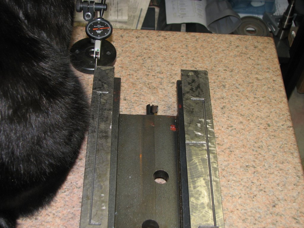 |
 |
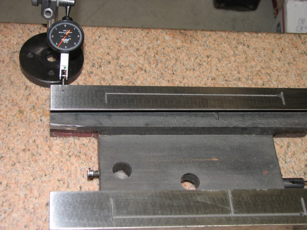
| Next
to
the
cat,
we
see
the
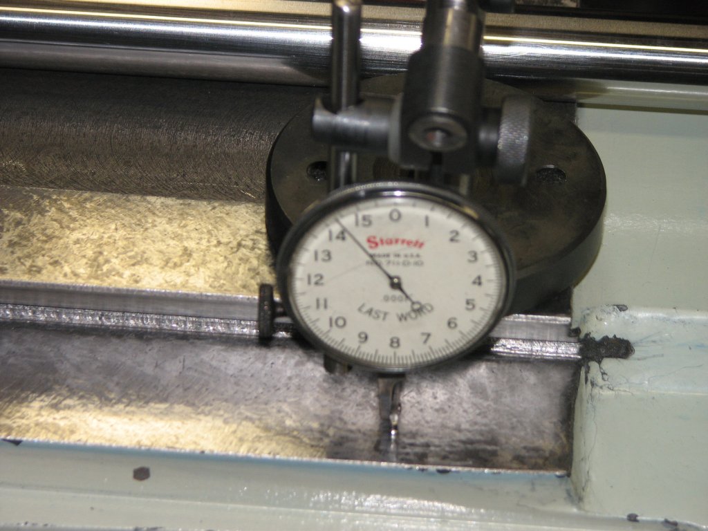
indicator reading a little less than 0.002" - and
signs that a grinder was used to 'precision' adjust these ways. |
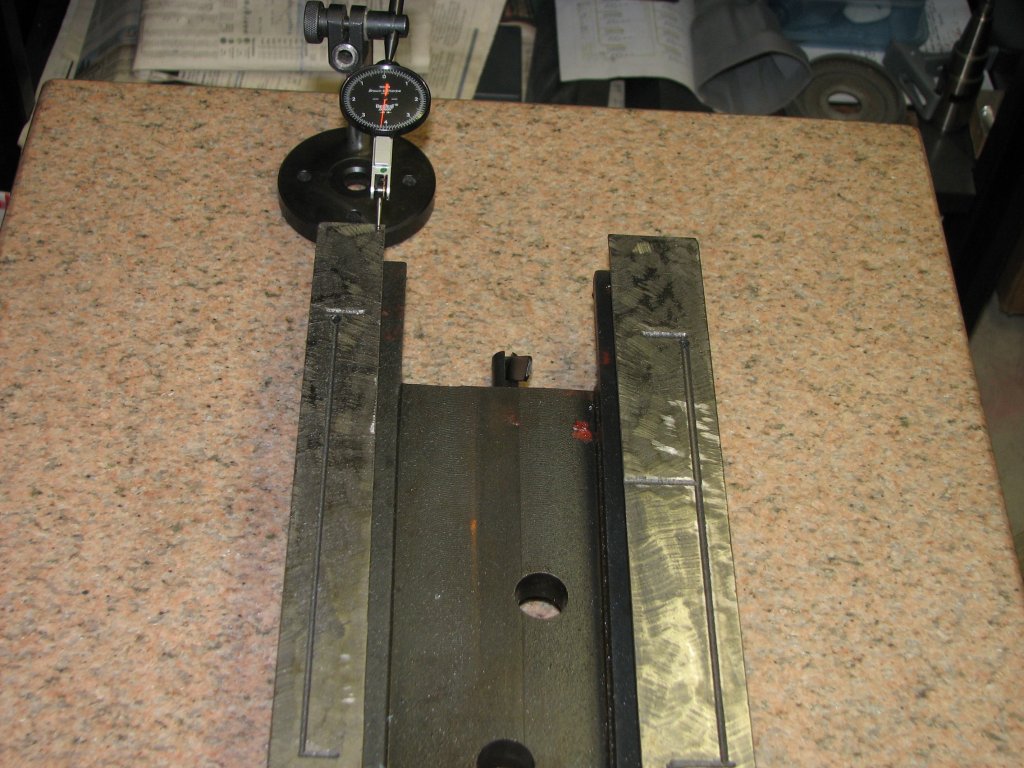
The
reading
is
now
over
0.004"
That's
2 thousandths in about an inch. That's a lot
of tilt for one inch of linear distance; and there's more... |
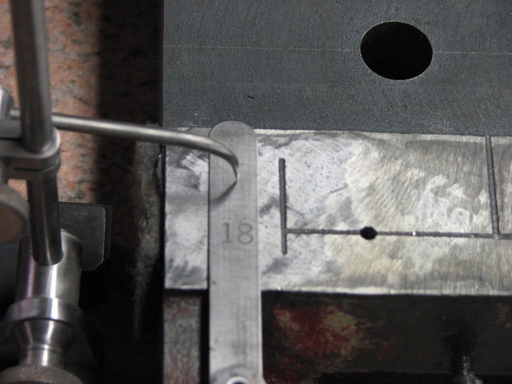 |
 |
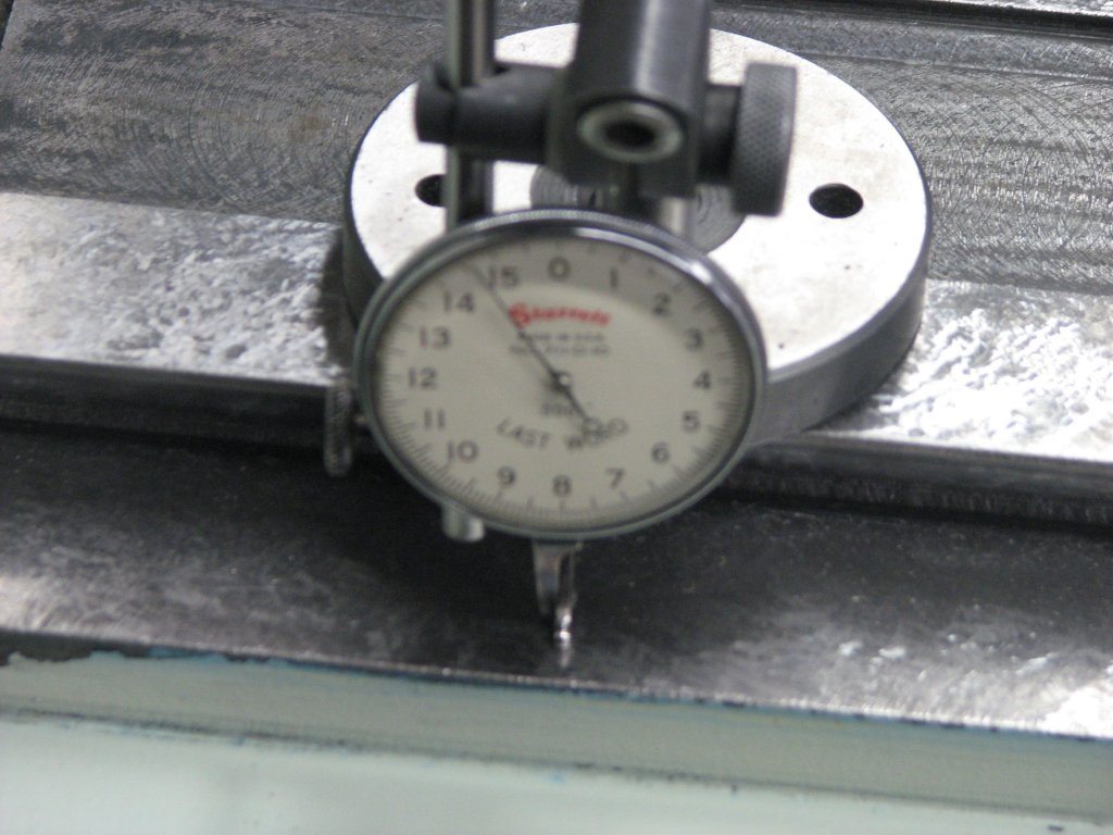
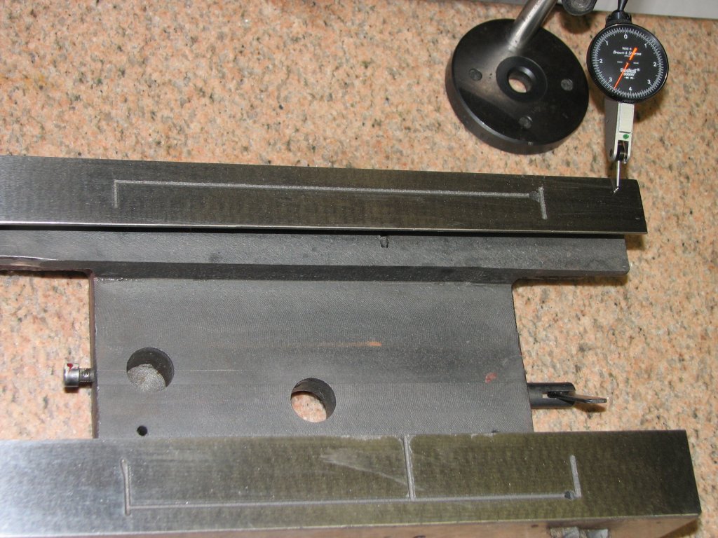
| From
one
side
of
the
saddle
ways
to the other, we have ~0.018" height difference. This is on the Y
ways. The Z ways are further apart, so worse. |
It
doesn't
appear
that
much
of
an
attempt was made to finish these ways
with any sort of accuracy in mind. Very ugly workmanship. |
It could be that
this mill is an isolated case of a "bad unit" making it through the
manufacturer's
usually exemplary quality control process. However, based on what
I have seen with this mill, it appears that rather than fix the problem
with the knee not fitting as it should have, they did whatever it took
to get this one out the door. I just happened to be the lucky guy
who got it.
So, my task becomes
reworking this saddle so that the following conditions are met:
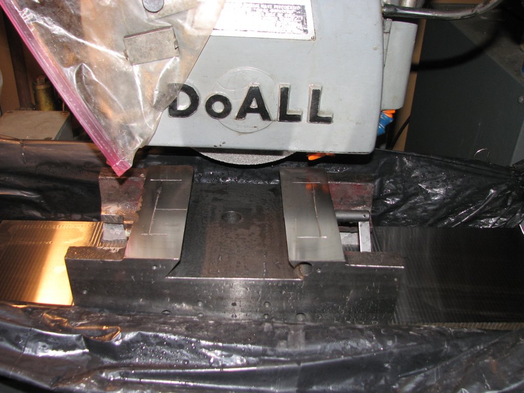 |
 |
| The
chuck's
been
cleaned
and
the wheel dressed. |
The last passes on the Y ways have been ground. |
 |
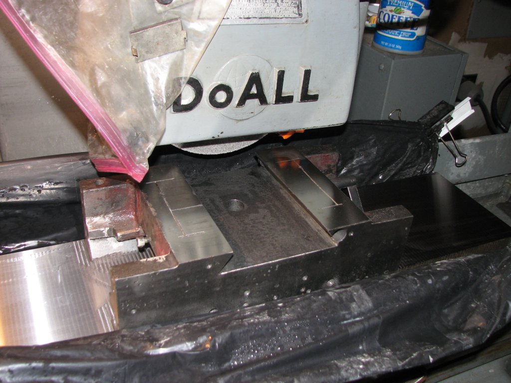
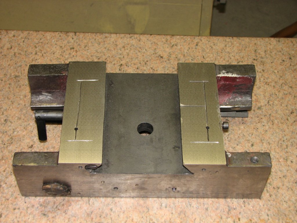 |
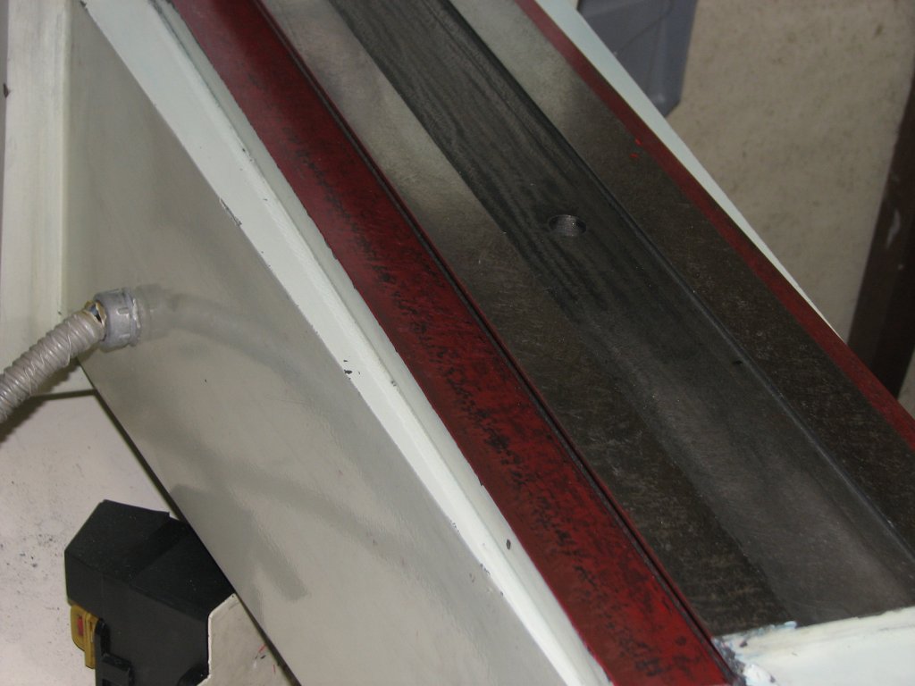
| A
view
of
the
X ways after surface grinding. The two holes between the
ways are for the X and Y leadscrew nuts. The X hole is near, Y is
behind it. |
The
Y
ways
were
ground again to make sure that they were parallel with the
X ways. You can see that it's pretty thin above the way adjusting screw. |
 |
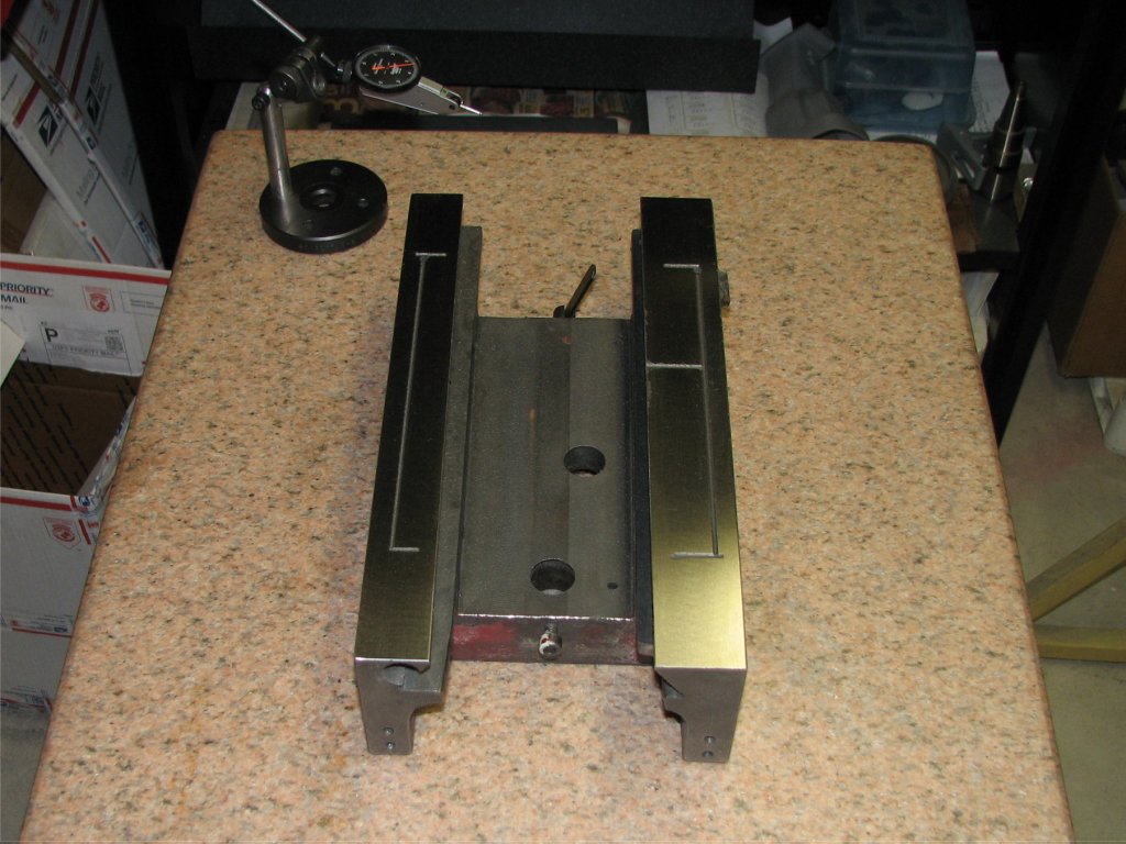
 |
| With
the
saddle back on the surface plate after being ground, I measure all
4 corners of both sides. There was less than 0.0002" difference between
the highest and lowest measurements. |
I
have
a bit of a pattern showing in the ground surfaces. I hadn't
seen this in other pieces I've ground, so I did some looking. The
spindle belt has some cracks in it. Looks like I need a new one. |