|
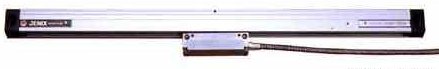
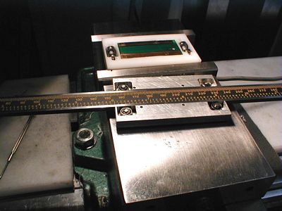
The
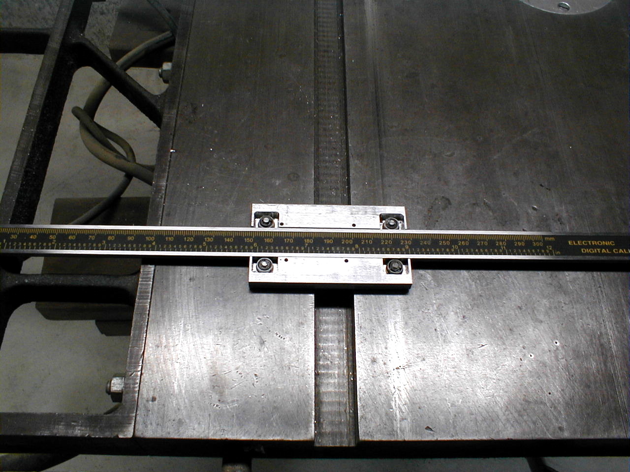
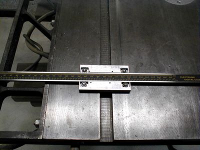
Jenix JSN5L 450 mm scale.
|

|
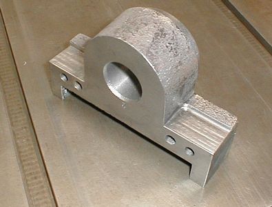
A
QCC-100 gets assembled.
|

|
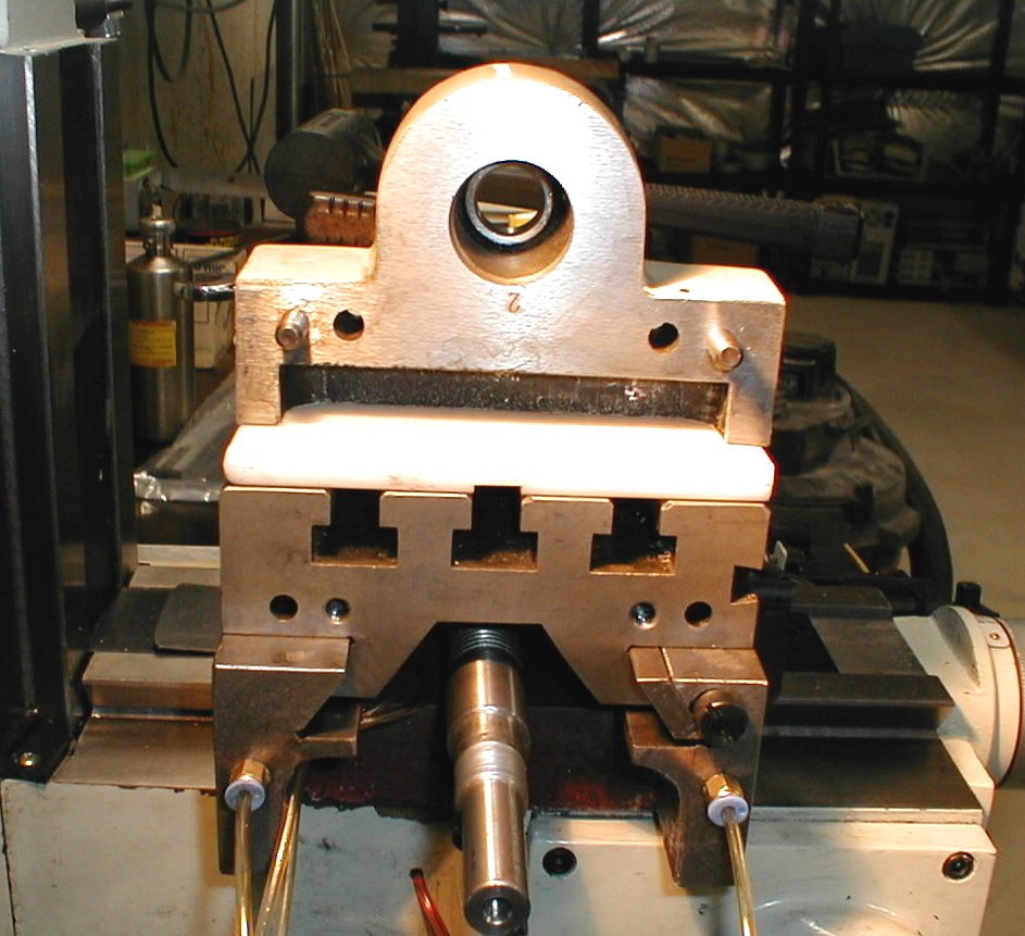
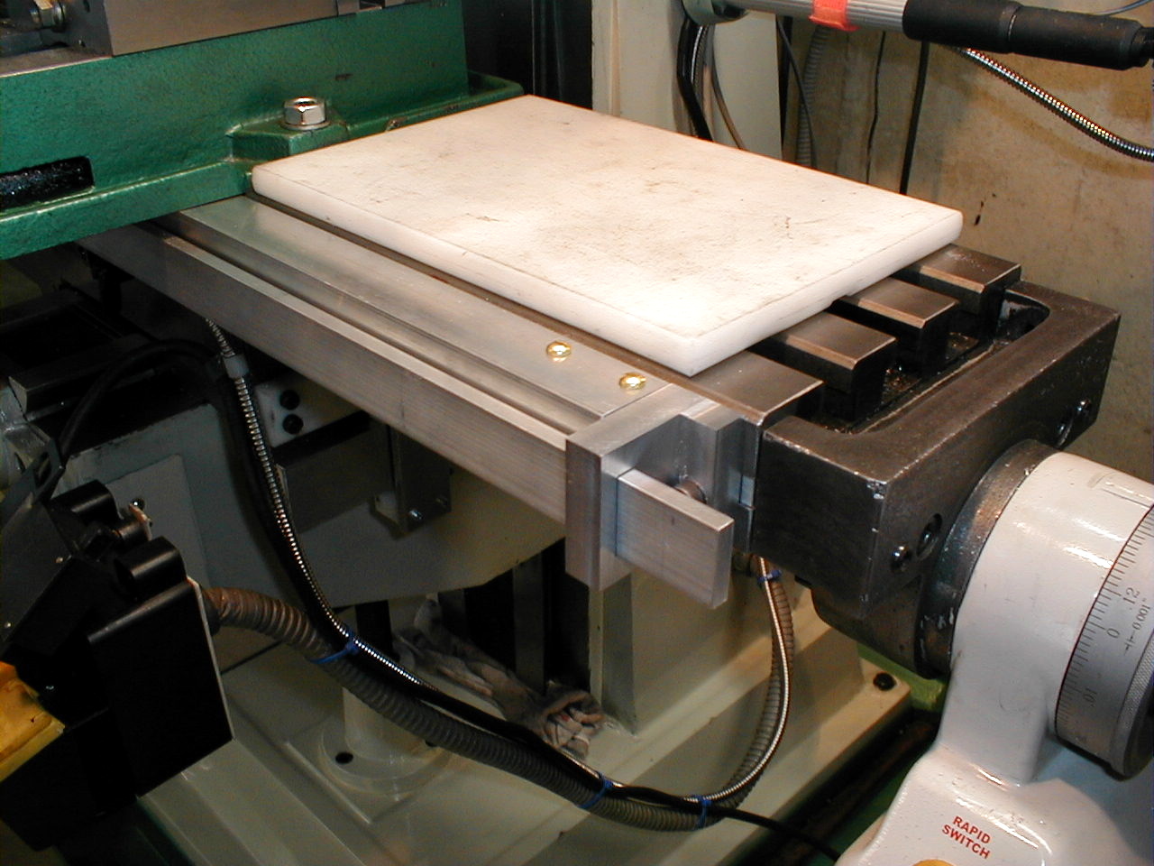
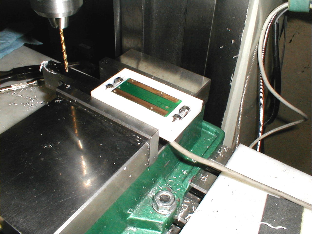
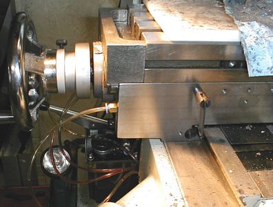
Getting
ready to machine the end caps.
|
|
Done.
|
|
An
extra inch or so travel is gained.
|
|
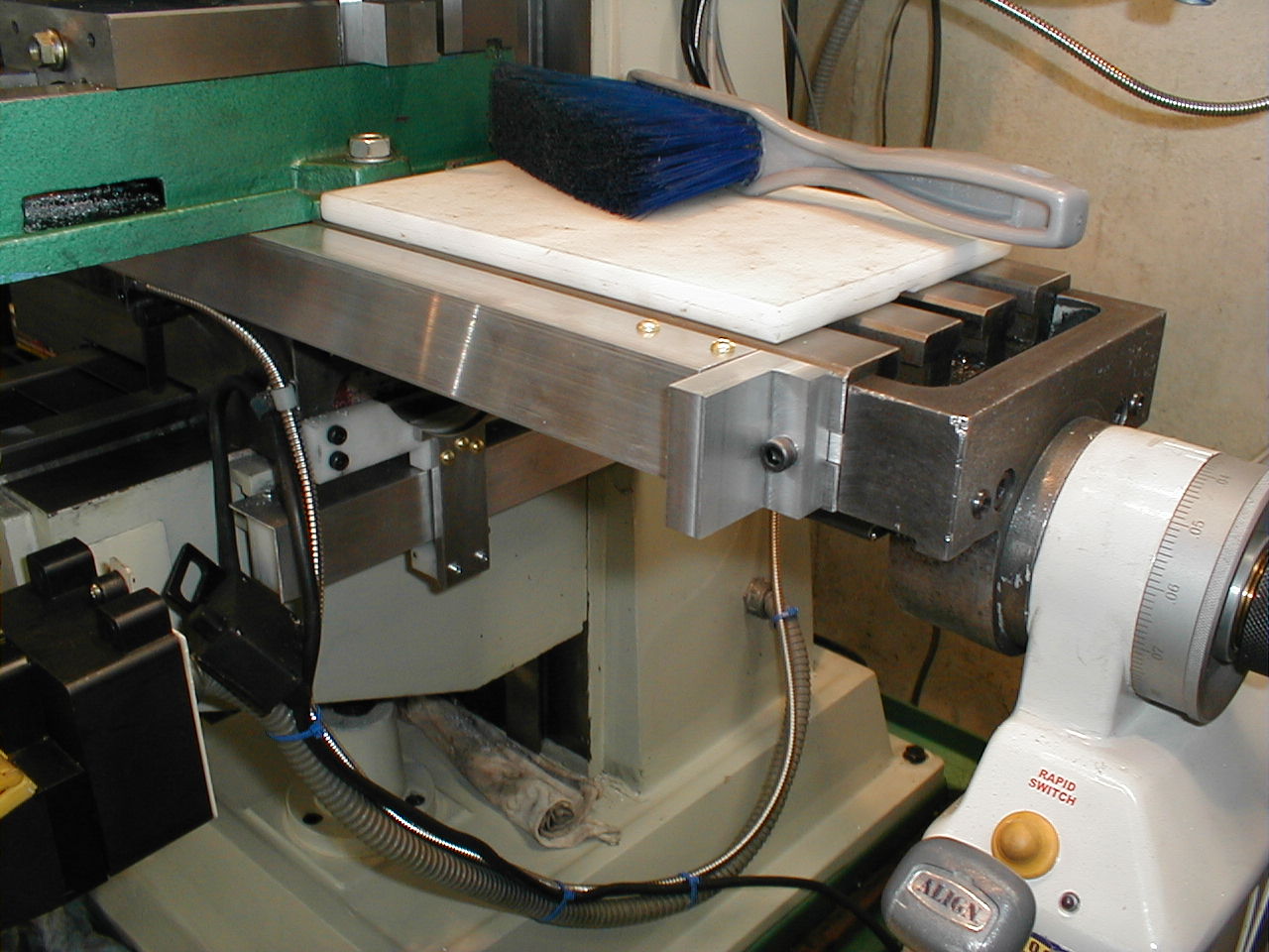
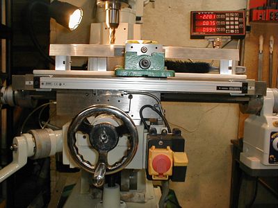
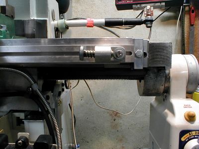
The
Jenix scale is installed
|
|
The
angle aluminum is added to protect the Jenix.
|
|
One
bracket added for the new adjustable end stops.
|

|
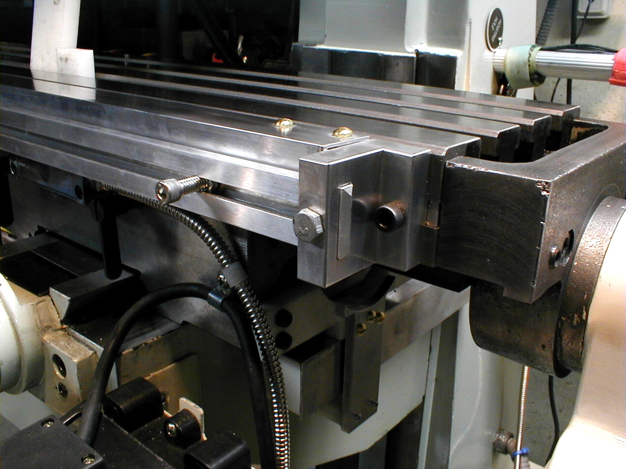
The
second bracket. Check out the nice chip in the end cap that was
hidden beneath Bondo.
|

|
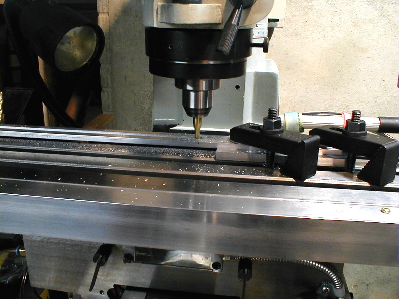
Slots
were cut and the beam is test fit.
|

|
The
beam gets its own slots.
|

|
Testing
the slots and captured nut behind it.
|

|
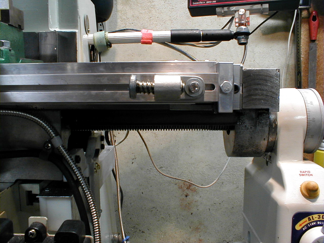
I have
adjustable end stops again!
|
|
Adjustable
with a hex head wrench.
|

|
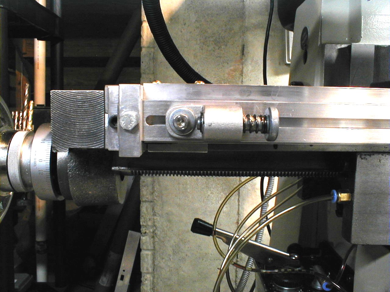
Same
for the left side.
|

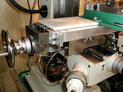
|
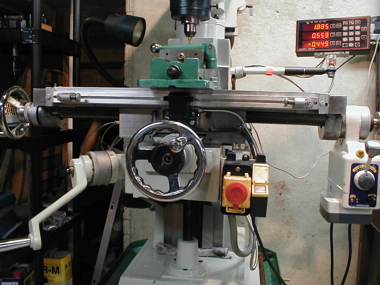
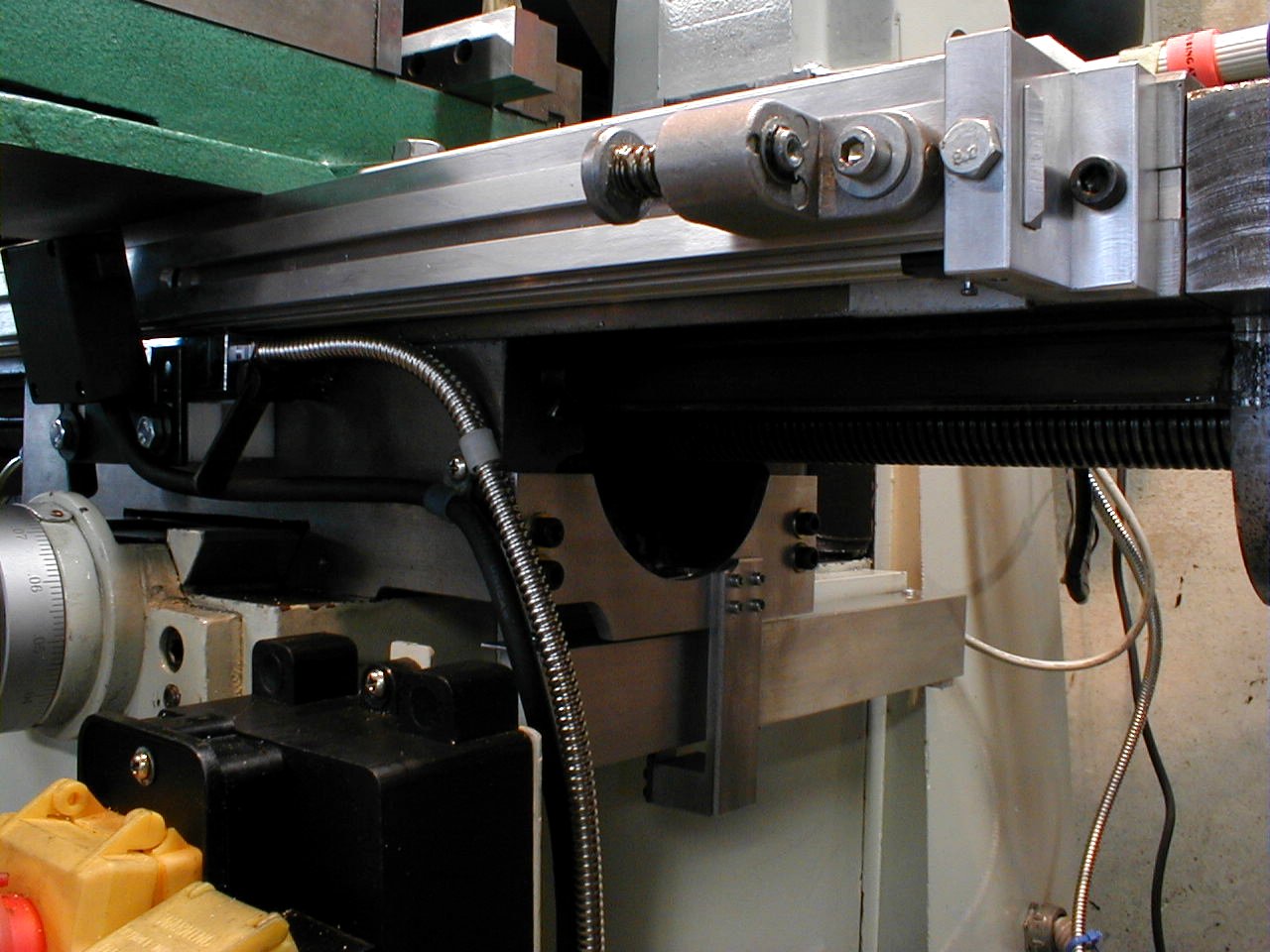
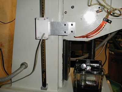
One
more view and a dark shot of the re-vamped Y axis mount. Aluminum
stock was used this time.
|
|
Let's
add some ball bearings to a Chinese caliper.
|

|
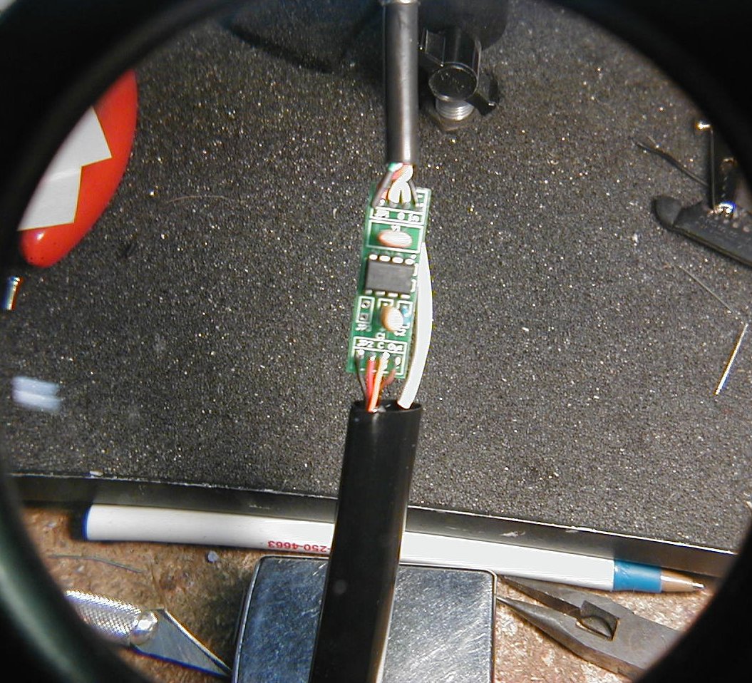
The
circuit board fits.
|
|
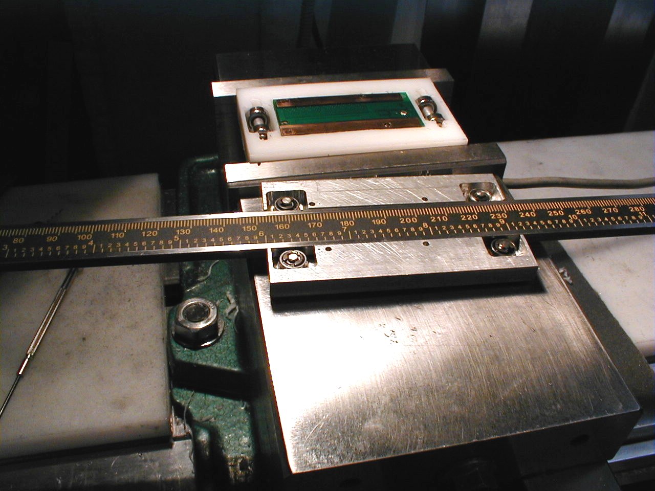
Tab A,
slot B, and put them together.
|
|
A
solid mount - 0.25 X 2.0" aluminum.
|

|
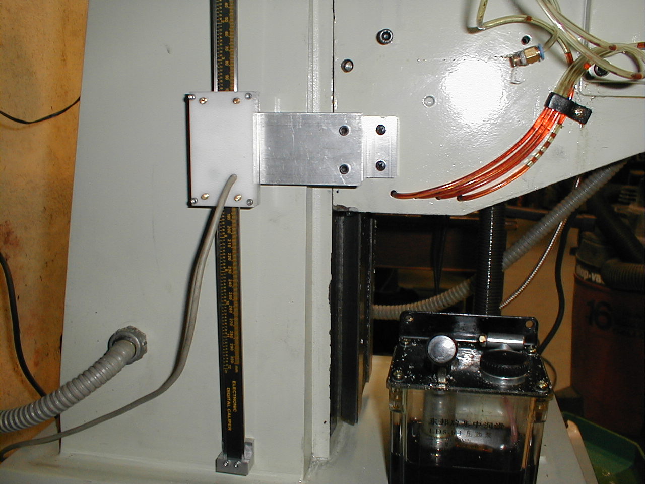
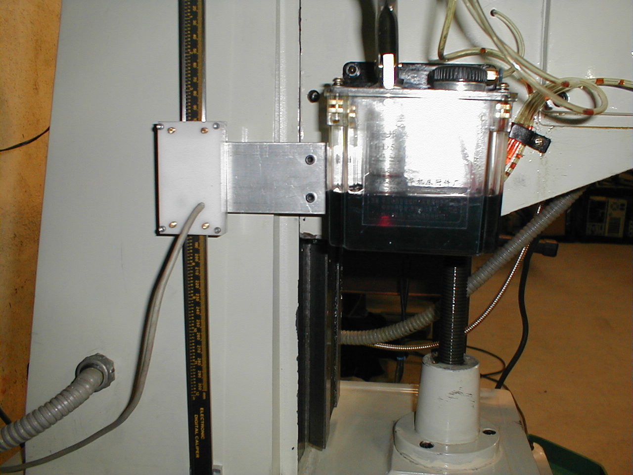
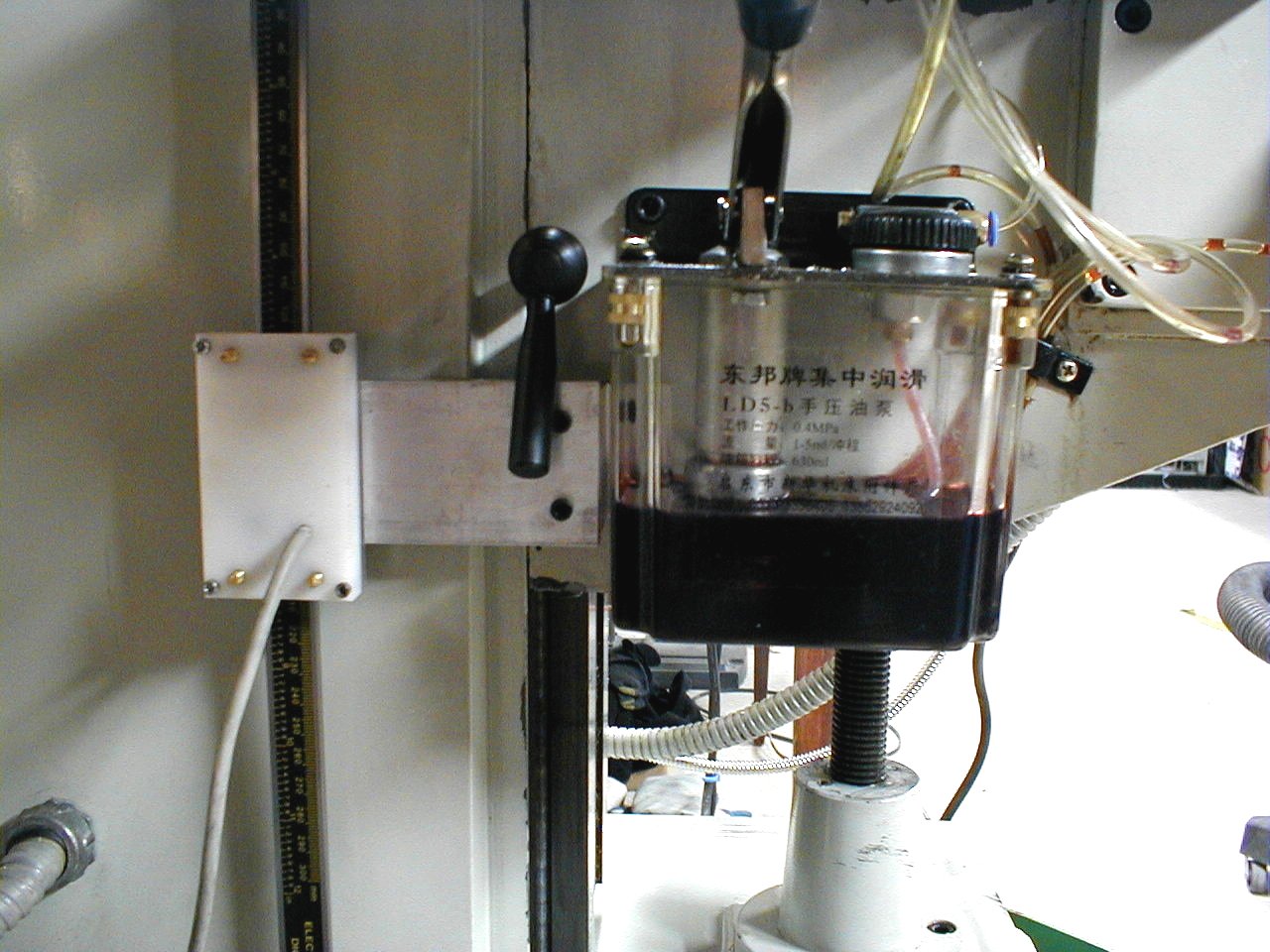
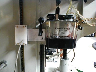
The
one-shot lube gets attached.
|
|
Job
finished.
|
|
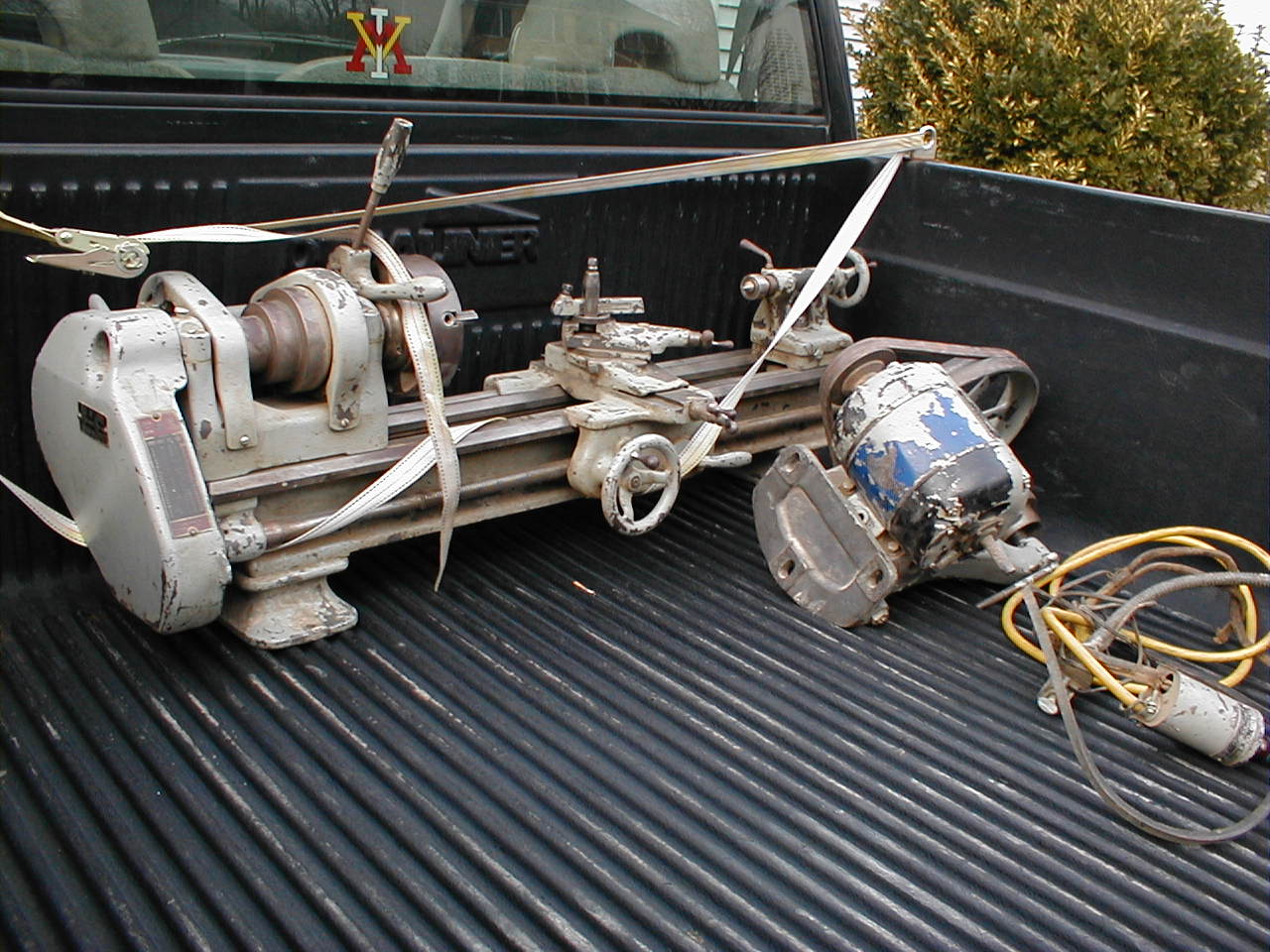
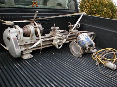
Next
project!
|
|
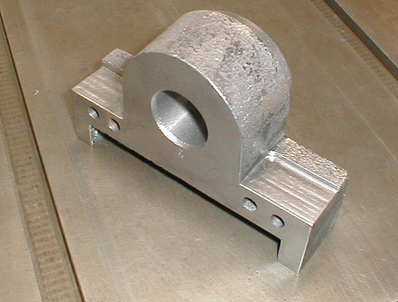
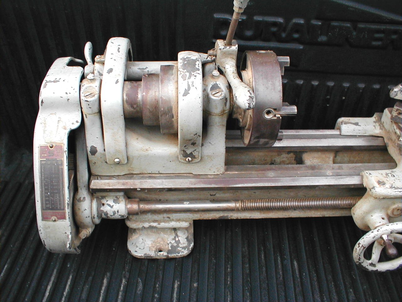
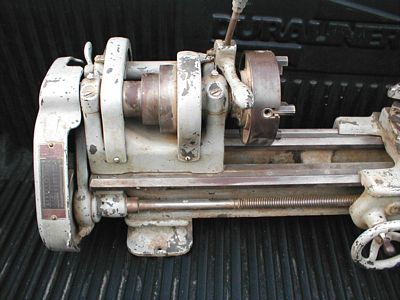
A 1934
South Bend 9" workshop lathe.
|

|
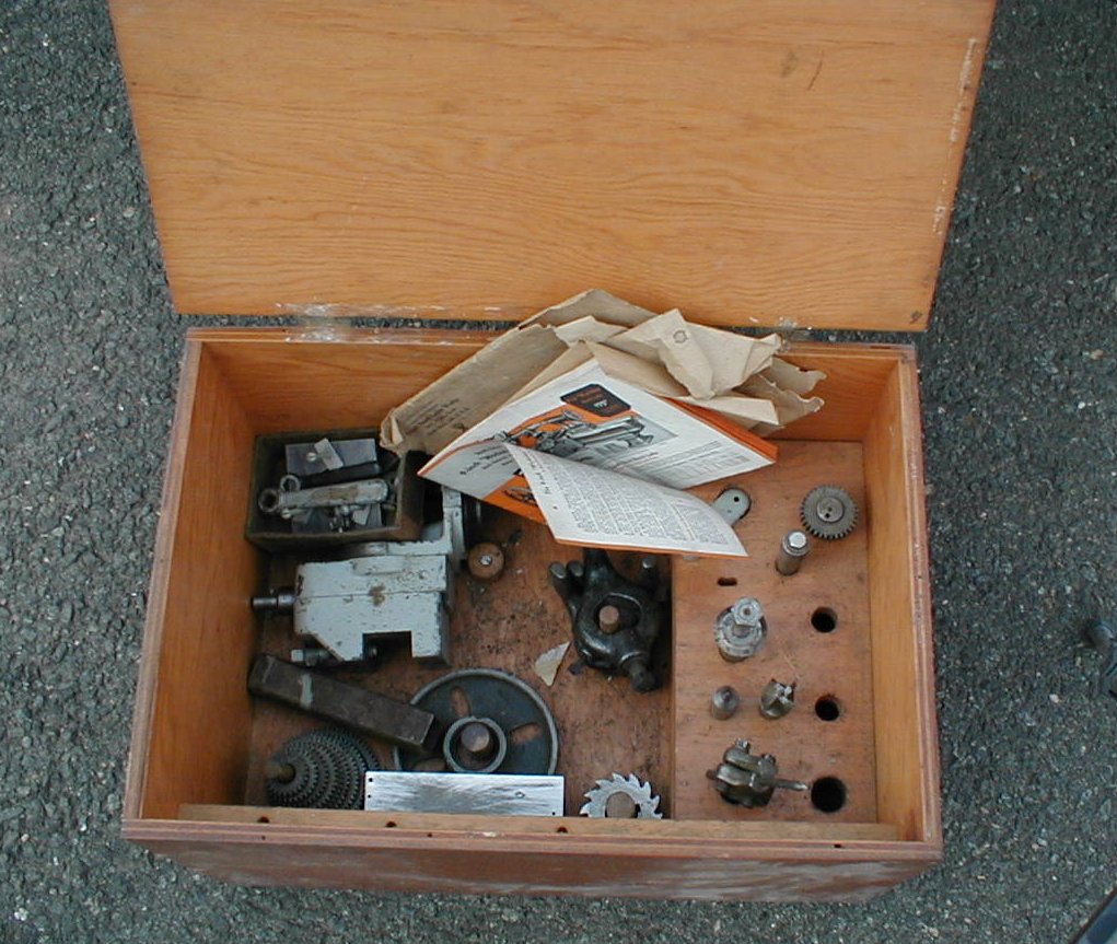
Some
goodies - including a milling attachment and the original 1934
literature.
|