Sheldon 12"
Shaper - pg. 4
August 18, through September 27, 2015
At this stage in
trying to get the Sheldon shaper to cut square and true, the
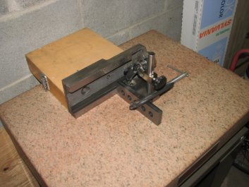
shaper's vise was waiting for me to plane it on the shaper.
However, before this could be done. I needed to take care of some
of the issues I had noted when I was cleaning up the shaper.
Since I had the tool head
and the adjoining swivel block removed from the ram, I decided to
see if I could figure out why the tool head gib adjuster was
standing proud of its alignment hole. In the second installment, I had
noticed that the screw that held the tapered gib of the tool head
slide stuck out from the gibbed way enough that the collar of the
adjusting screw wasn't seating fully in its hole. This didn't seem
right, especially considering that this machine obviously had some
wear. All else being equal, the more wear on the tool head
dovetail ways, the deeper the tapered gib should seat. I was
also having trouble locking the tool head from moving during cuts.
I had already had the tool head apart once when I cleaned it, but,
at that time, I didn't do any measuring or put the parts on the
surface plate to check their flatness.
This time, I would inspect the tool head a little more thoroughly.
I again pulled off the crank handle, removed the Acme screw, and
took the tool head slide off of the swivel block. I then put the
tool slide bottom ways on the inked surface plate. When I checked
for color, I had only three contact points. One point on each end
of one way and a very thin stripe of color on the outer edge of
the other way. The thin stripe of color on the edge of the way was
puzzling. The edge of the sliding way had a raised burr where the
flat way met the side of the tool head and it had dug a
corresponding groove in the swivel block surface. I have no
clue what could have raised this small jagged edge. The front
surface of the swivel block that the sliding tool head attaches to
has no defined flat ways. There's just two semi-circular flat
areas and some of that is used to support the tool head bottom
ways. I used a fine toothed, single-cut file to get rid of the
ridge on the edge of the tool head way and took another print. Now
I had two spots on both ways. Each spot was at the ends of the way
surfaces. It seems that the tool head ways were a little concave.
Generally when rebuilding a sliding fit, the longer surface is
scraped flat and the shorter surface is scraped with a slight
depression of a thousandth or two covering the center 40% of the
ways. As the shorter surface wears, which usually happens on the
ends of the ways first, the depression eventually comes into
contact with the mating ways. Without the slight depression, the
ends of the ways would wear and the shorter member would rock on
the mating ways. In this case, it was the longer member that was
slightly concave when it should have been flat.
In the couple hours total that I have run this shaper, I have
noticed that the tool head and the attached cutting tool tend to
creep down while cutting. This isn't a good thing at all as you
end up cutting deeper and deeper into the work. There is a lock on
the tool slide that one would expect to stop this from happening,
but it didn't. Also, the tool head gib screw seems to sit too
high. On the rest of the gib adjusting screws, the cylindrical
collar on the screw fits into a cylindrical pocket. On this one,
the screw collar stands above the pocket by about 1/10".
When I try to adjust the gib, the screw is pushed away from the
gib toward the center of the swivel block. This makes it difficult
to get a proper adjustment between the tool head and swivel block
ways. To get the tool head to lock, I tried cranking down the lock
screw pretty firmly, but to no avail. I finally stopped the creep
by tightening the tool slide gib almost to the point of not being
able to move the slide and placing a piece of copper sheet between
the lock screw and the tool slide to increase the friction as I
cranked the lock snug. Something wasn't right.

|
|
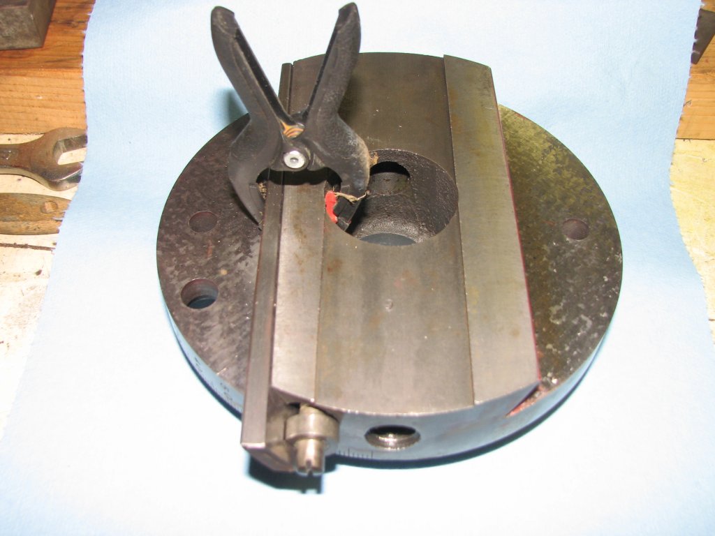
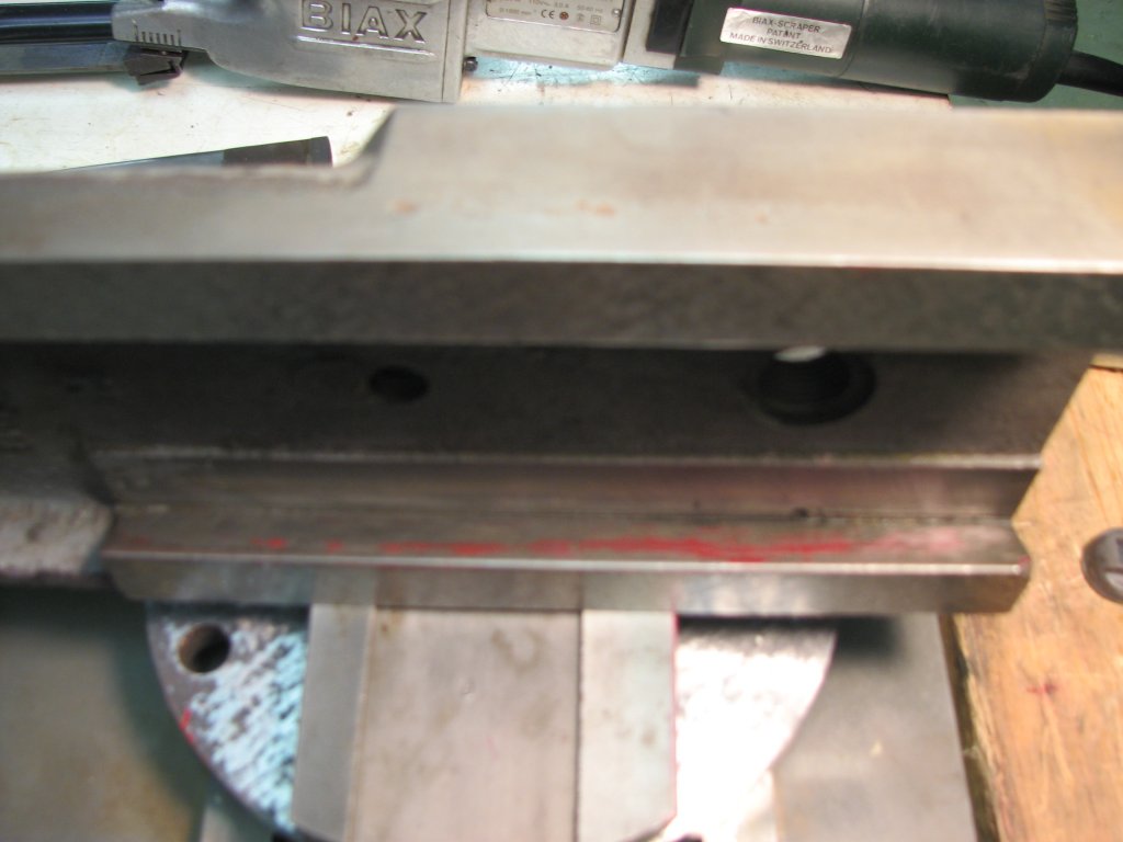
This
photo shows how the gib adjusting screw was when I
received the shaper. The cylindrical collar on the screw
did not seat into its hole.
|
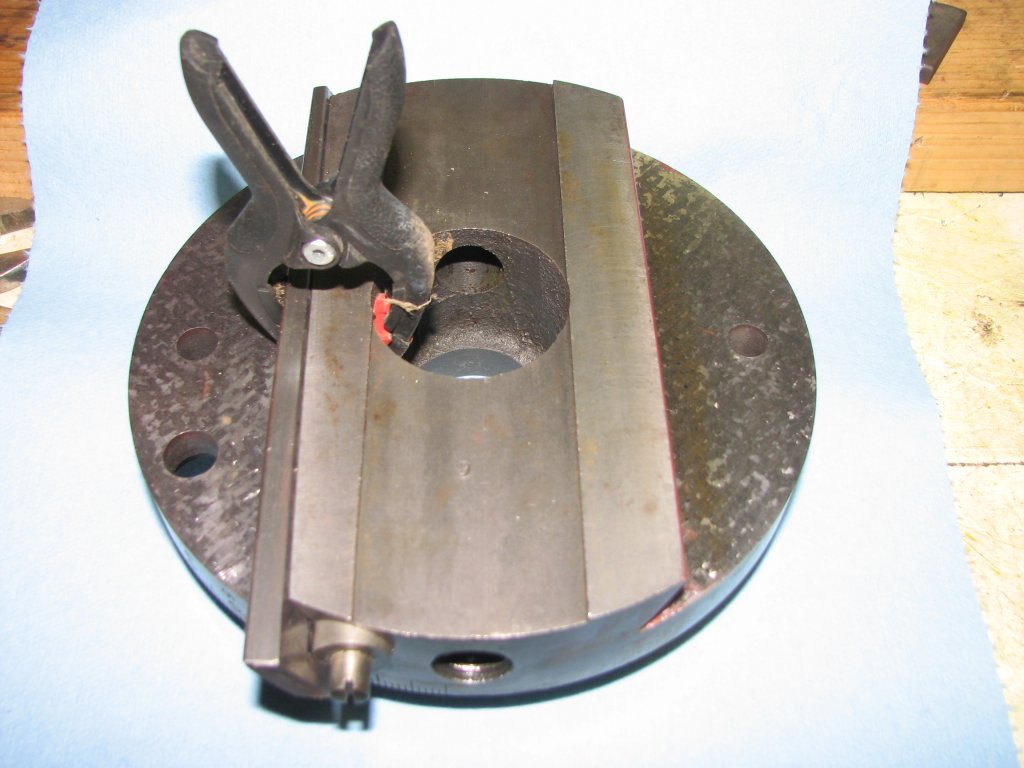
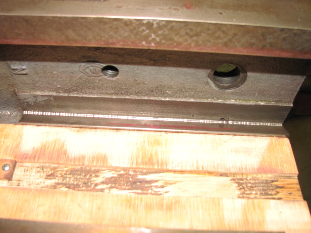
This
is how the screw should fit into its supporting hole.
The hole is drilled deep enough for the screw to go
deeper if needed to adjust the gib.
|
In the reading I did before I powered up the shaper, I'd
read that you should adjust the tool head so that you are raising
the slide when you lock it. This removes the backlash that you
would have if you locked the slide while moving the bit toward the
work. I used this method from my very first cut without it helping
the situation at all. I will give the lock situation some more
thought and revisit it after I scrape the ways.

|
|
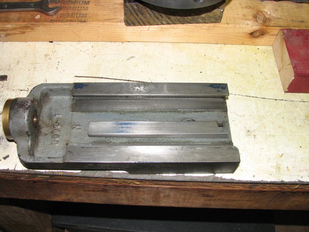
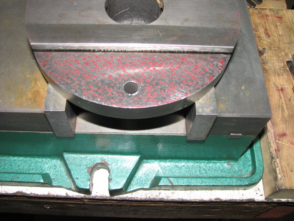
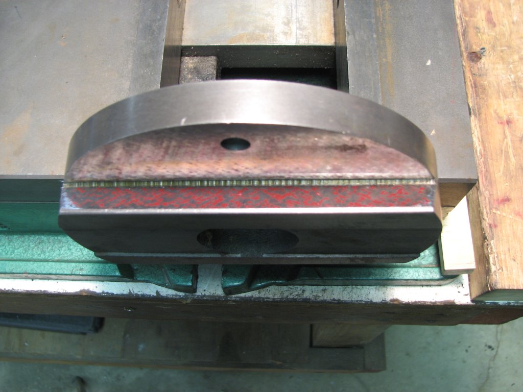
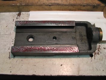
The
tool head slide bottom ways are showing very little
contact when printed on a surface plate. The non-sliding
side of the gib also shows next to no contact and is a
bit bowed.
|
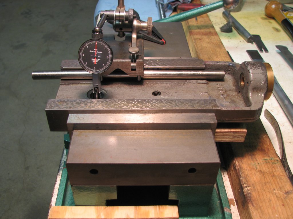
I've
marked and scraped a few passes. I'm starting to see
some color, but don't want to scrape too deep yet due to
the fixed position of the Acme screw.
|
As I thought about the tool slide operation, I realized that both
the crank end of the Acme screw and the end that threads into the
swivel block were fixed in their position. Unlike the cross slide
of my South Bend lathe, there was no movable nut to keep the screw
parallel with the ways as they wear. As the tool head ways wear,
the bushing on the tool slide that supports the Acme screw, drops
in relation to the threaded hole in the swivel block. Since the
swivel block ways also wear, this increases the angle of the screw
in relation to the plane of the ways. Since I am scraping these
surfaces, the more I scrape, the less parallel the screw will be
to the ways. Once I get the flat ways scraped on both the tool
head and swivel block, I will reassemble the pieces and check to
see how the Acme screw aligns.
After a few passes with a hand scraper, I was
getting some color on the tool head bottom ways. Both of the
inboard edges of the ways were low. I scraped a few more passes
and one of the ways now had pretty good bearing, but the other
still had no color along the inside edge. I figured that I had
scraped about two thousandths deep and had a thousandth or three
to go to get the bottoms of the dovetails flat with full scraped
coverage. However, in consideration of the screw alignment, I
think I will just refine the surface a bit and scrape the swivel
block ways. I will then put it back together and see how
parallel the Acme screw is. If I can scrape deeper to get more
bearing on the bottom tool head ways, I will.
|
|
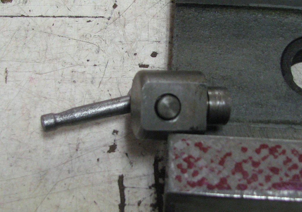
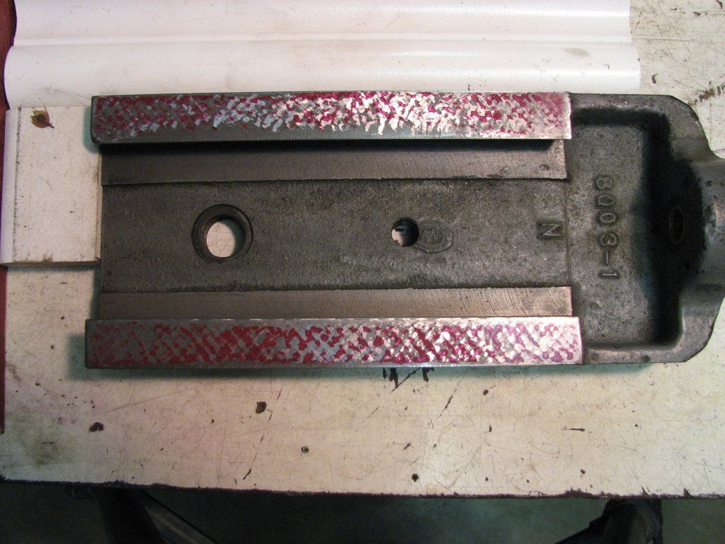
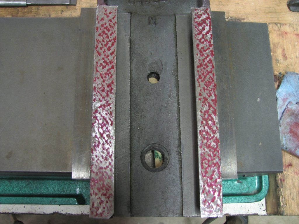
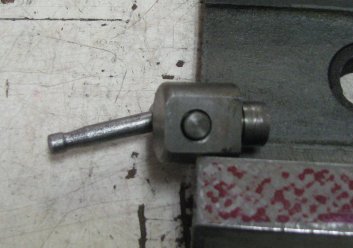
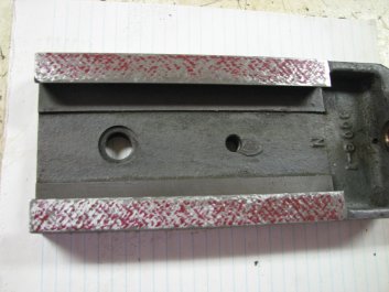
This
is the tool slide lock. The center of the lock screw has
been polished a bit. It does not do a good job of
locking the slide.
|
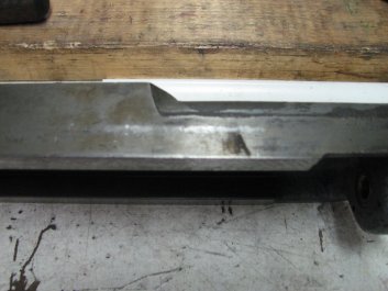
The
shiny stripe on the side of the tool slide shows that
the lock has been slipping or the slide has been
operated without releasing the lock.
|
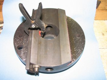
The picture above left is the tool head lock.
The circle in the center of the flat area is the end of the
screw that pushes on the outside of the tool head to attempt to
lock the slide. The cylinder to the right side fits into a hole
in the swivel block and is secured by a bolt from under the
swivel block. The bolt is sunk into a circular pocket that
doesn't leave enough clearance for the thinnest wall 1/2" socket
I own. I'm not sure why it's designed so that it is possible to
rotate the lock if the bolt loosens. I would think if you were
trying to lock a sliding member, you'd make the lock so it
couldn't be rotated. Not being able to get a wrench or socket on
to the securing bolt doesn't help much either. Since the body of
the lock was loose and has been able to rotate, the face of the
locking screw is now somewhat dome shaped from wear. It is also
has a polished finish from sliding against the outside
surface of the tool slide. The picture above on the right shows
a shiny stripe where it appears that the lock has been slipping
against the surface of the tool slide.
The more I think about the tool head lock, the more I question
the wisdom of the design. With the lock designed to put pressure
on the outside of the gibbed side of the tool head when
tightened, it applies pressure to the gib against the swivel
block dovetail way. So far, so good. However, by applying
pressure to the outside of the tool head, it moves the opposite
side of the tool head angled way away from the swivel block
angled way. In other words, it locks the gibbed side and loosens
the opposite side. This doesn't seem like a very rigid way to
lock the tool head.
|
|
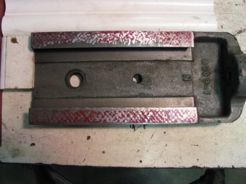
Rough
scraping the bottom ways of the tool head.
|
A few
cycles later. Both inner edges are slow to get color and
I am concerned about scraping too much material off.
|
I am a bit torn between my wanting to keep the shaper stock and
wanting it to be a tool that I am confident in using. It would be
easy enough to drill and tap for a locking screw that put pressure
on the tool head gib, but I don't want to modify the machine until
there is no other choice. I admit that the more I learn about old
machine tools, the more I want to preserve the ones I own in their
original state as much as possible. However, I also want to
use the machine. That's why I bought it. If I am unable to control
the depth of cut, it's going to be very difficult to use. Once I
get the tool head and swivel block scraped, I will find some way
to keep the lock from rotating and I will put a new surface on the
tip of the locking screw and plane some metal. If the lock still
doesn't work, I will consider my options.
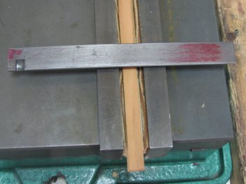
With the bottom ways of the tool head slide rough scraped, but not
finished, I moved on to the tool head's swivel block. I will
scrape the surfaces that mate with the ways on the slide so that I
can measure for how parallel the Acme screw is with the ways. When
I inspected the dovetails on the sliding member and the swivel
base, I noticed that there were no grooves cut at the vertex of
the dovetail ways. Instead, there is a small fillet. This is the
first machine tool I have scraped without slots at where the angle
way meets the flat way. Connelly has a chapter in his book
"Machine Tool Reconditioning" about dealing with the lack of
grooves and I re-read it. I decided that I would add a small
groove at the vertex of the angled ways so that I could more
easily scrape into the tight angle. I added the slot with the edge
of a 1/16" carbide scraper blade by pulling it along the vertex. I
dug out about 1/16" deeper than the tip of the angle. This
is just enough to allow my hand scraper blade to get into the
corner and scrape both converging surfaces flat. I'll use the hand
scraper for the getting into the corner and the Biax for for the
rest of the surface.
|
|
The
left dovetail has had a groove added to the vertex of
the angle.
|
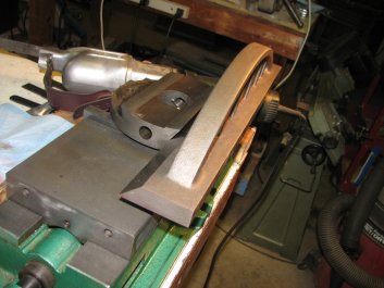
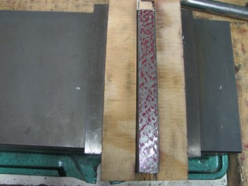
Making
a print of the swivel block flat ways using a camelback
casting that I previously scraped.
|
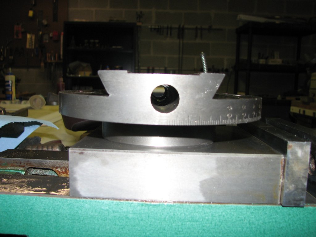
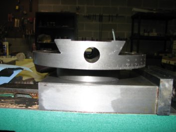
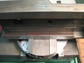
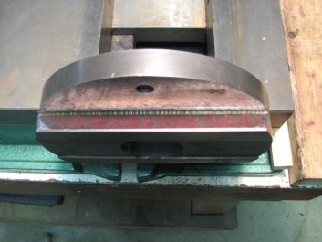
Before I started scraping the swivel block, I set it on some
parallels on the surface plate and measured the top surface. The under side of the swivel block is shaped
like a top hat. The bearing surface that mates with a circular
area on the end of the ram would be the brim and the cylinder that
fits into a 3" hole is the extended cylinder above the brim. The
picture above left shows a little of the cylinder that fits into
the hole on the end of the ram. I was surprised to find that the
face that the tool head mates to was not parallel with the
circular ways on the face of the swivel block. One side of the
semi-circular surface was angled by about 0.003" over the 6.5
inches to the left. The other side way angled about 0.0015" to the
right. I was going to need to lower the top surface of the swivel
block by at least three thousandths to get it parallel with the
underside bearing surface.
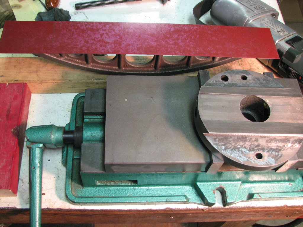
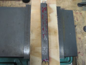
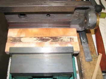
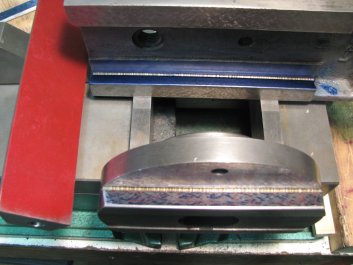
Marking the swivel block was done with my 24" granite knife edge
angle template and a 18" cast iron camelback straight edge.
While I prefer marking with granite, I am alternating between the
two. If consecutive prints don't match, I've picked up some swarf
that I didn't catch when I cleaned the swivel block or straight
edge. In the staged picture below left, I show the straight
edge close to the work. In actuality, the only time it's this
close to the work is when I am marking. The rest of the time, it
sits on the other end of the eight foot bench covered with some
closed foam insulation board to keep dust and swarf off of the
marking fluid. I also noticed that there are some metal flecks on
the vise in that picture. Normally the shop vacuum has already
been used to clean up and the area is dusted with compressed air
from my compressor and air chuck. Keeping things clean helps
prevent swarf from getting between the straight edge and work and
making you wonder where all of your bearing spots have gone.
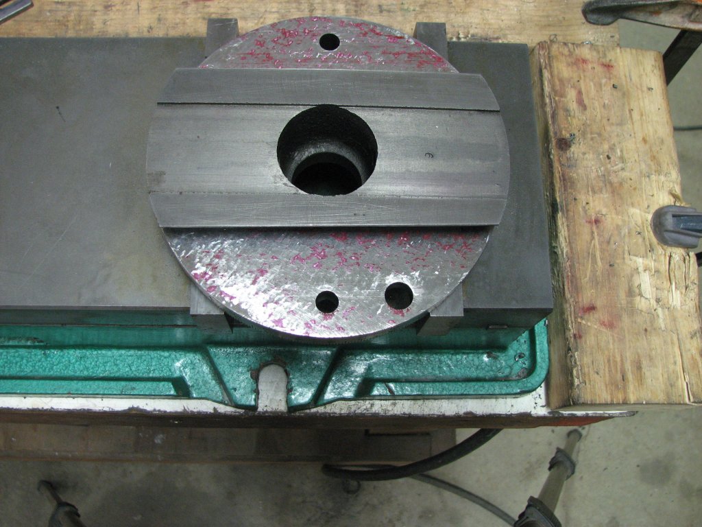
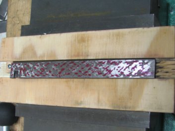
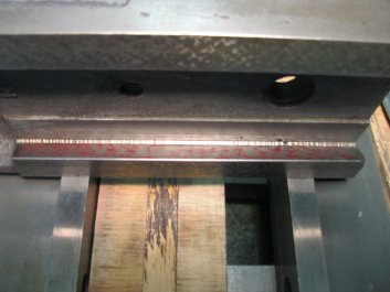
I am scraping most of the top surface of the swivel block with the
Biax. The only areas I am hand scraping are the tip of the
dovetail next to the groove, around the holes and the edges of the
circle. Trying to get into this tight a corner with so small of a
run-off groove with the Biax would result in the blade hitting the
bottom of the groove. I'd rather scrape to within an eighth inch
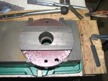
or so and follow up with the hand scraper. In the picture below
right, you can see a faint line that marks where the ways of the
tool head rub on the swivel block. This area was only worn a
little under thousandth deeper than the rest of the surface, but
there is a fairly deep scratch on the side with two holes that was
caused by the raised edge on the outer tool head way. Aside from
aesthetics, the scratch won't affect anything since it's below the
bearing surface.

|

|
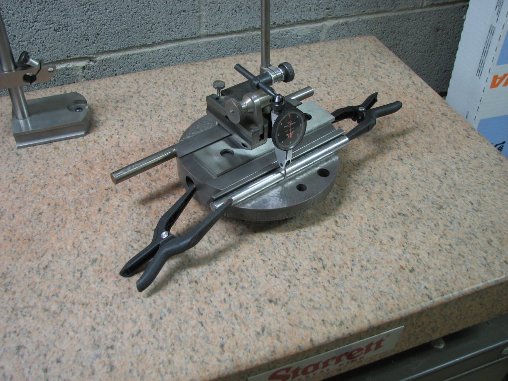
These
are the tools for holding and marking the swivel block.
I keep the straight edge away from the scraping and
covered with a piece of foam.
|
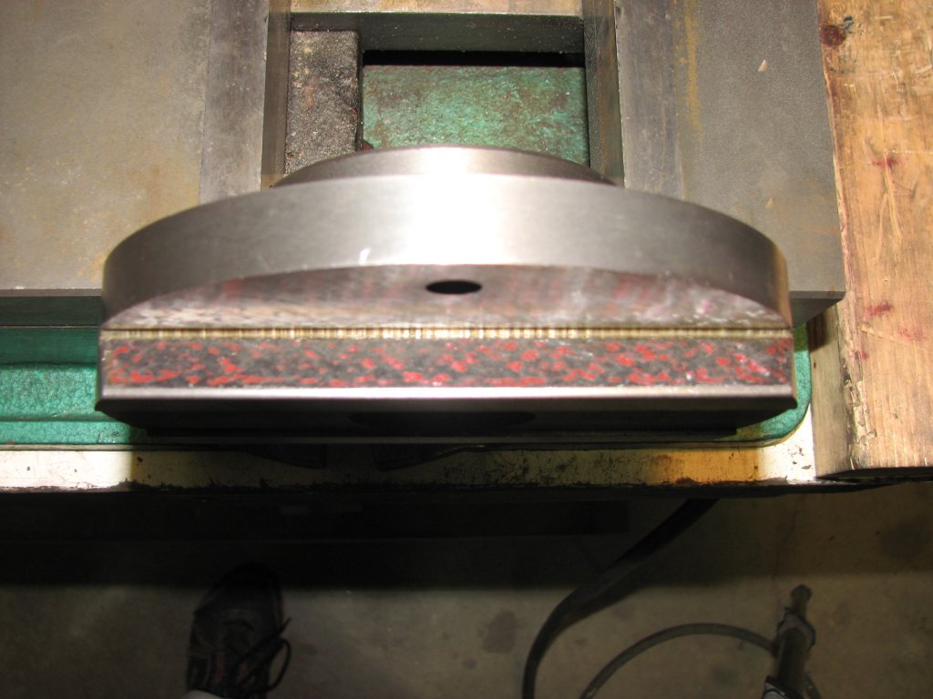
The
section of the swivel block where the tool head ways
mate was about 0.001" lower than the rest of the
surface.
|
When working on flat ways in the same plane, such as the bottom
ways on the tool head, I would normally scrape both surfaces at
the same time. I'd print both surfaces and scrape both surfaces. I
find this helps me to keep the amount of metal I am removing about
even. However, since I had two planes angled in opposite
directions, I chose to work on the side that needed the most metal
removed first. I step scraped the side with the two holes until I
had the surface parallel with the lower bearing surface to within
a half thousandth. I then switched to the other semi-circle and
rough scraped that side until I had about the same height when
measured on the surface plate. I then began printing and scraping
both sides before printing again. About every third cycle, I put
the swivel block back on the surface plate to check that both
halves of the block were the same height as I brought in the
bearing points.
|

|
I am
starting to get some pretty good coverage with the
bearing points. Both semi-circles are now in the same
plane within a tenth or two.
|
The
bearing points on the opposite side of the swivel block.
I still need to scrape the angled way on this side. The
other side gets the gib.
|
As I mentioned before, the member with the
shorter ways is often scraped a bit hollow in the center to keep
it from rocking as it wears. However, since I was having trouble
with locking the tool head, I decided that the more contact area
I had, the better chance I had at getting the lock to work. I
ended up scraping both semi-circular areas flat. rather than
relieving the center 40% of the ways. With the swivel block
surfaces scraped, I assembled the tool head and checked the fit
of the Acme screw. It seems to be OK. It's a little difficult to
measure the angle of the screw as it is hidden between the two
parts, but it turns smoothly with no binding when the tool head
bushing and swivel block threads are at their closest points.
Since the screw turned well, I decided to scrape the tool head
flat ways to better bearing. After scraping them, there is still
a bit of a low area on the inside edges of the tool head flat
ways, but I have a lot better coverage than I had before and
don't want to remove any more metal from these ways. Once I reached the the
bearing shown in the picture below left, I made a few more
passes to split some of the larger points and called it
done. The last few passes also brought in a little more
bearing at the ends of the ways.

|
|
I
have now scraped out most of the low areas along the
inner edges. I still need to get a little better bearing
at the ends.
|
This
is the non-sliding side of the tapered gib. It may have
been replaced at some point. The spot to the left of the
cut-out is very high.
|
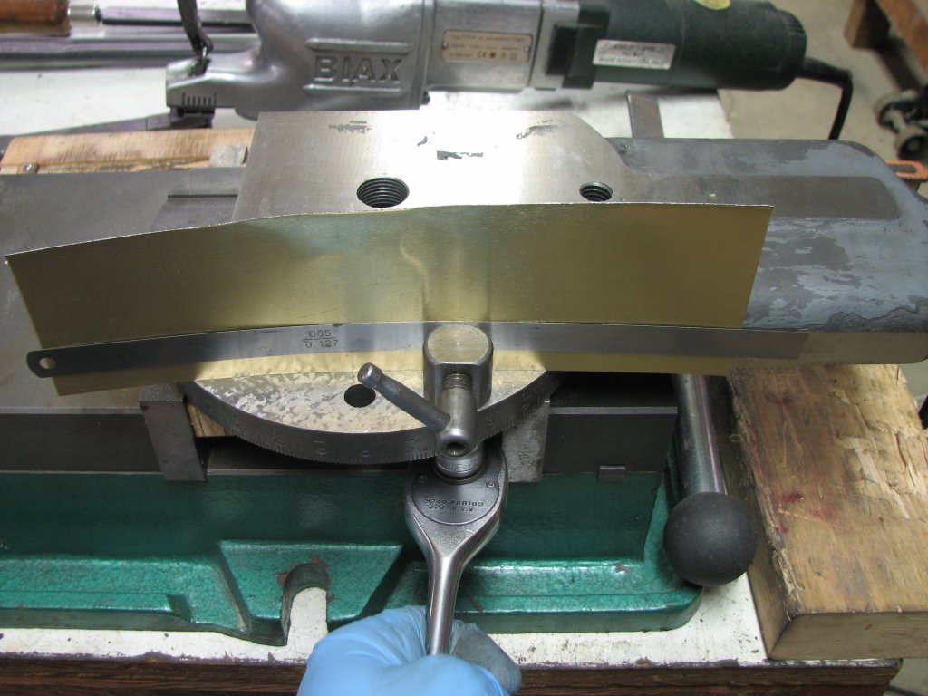
I checked both sides of the tapered gib for
bearing and flatness. There was a slight curve to the gib that I
needed to fix before I could get a true print. I was able to
slip an 0.002" feeler gauge under the center of the gib on the
surface plate. I took the gib to the hydraulic press and
supported the gib between a couple parallels with an dial test
indicator to measure how far the gib bent when I applied force.
It took a couple tries to get the curve out. Once I had a
relatively flat gib, I printed and scraped both sides. I checked
my progress by measuring for parallel between the two angled
ways as shown a couple pictures down. Scraping the gib went
pretty quickly as I wasn't looking for a high points per inch
count.
|
|
The
back side of the gib has been scraped.
|
This
is the initial print of the sliding side of the gib
after being straightened on the press.
|
The
next step was to measure the angled ways to get some
references before I started scraping them. I needed to know if
the angled ways were parallel with the flat ways I had
scraped. I was also curious if the machined flats on the sides
of the tool head could be used as a reference. After finding
surfaces that I would have assumed to have been machined at
the same time as the ram dovetails were not aligned, I didn't
hold much hope, but I was pleasantly surprised. The angled way
was within a half thousandth of lining up with the angled
dovetail and on the other side was about one thousandth from
aligning. The two outside flats were within a half-thousandth
of being parallel. I also added a couple precision shafts
along the angled ways and checked to see that the shafts were
parallel. They were parallel within a half thousandth over the
length of the angled ways.
|
|
The
sliding side of the gib has been scraped. Now it's time to
re-measure the dovetails so that I can keep the angled
surfaces parallel as I scrape.
|
Measuring
the angled ways with reference to the flat ways and the
machined flats on the outside of the tool head.
|
The next check was to see
if the distance between the swivel block angled ways was constant.
To check this, I needed to add the gib and measure, again using
the shafts which would contact the ways around their mid-point.
Half inch diameter shafts were just about the perfect size. I used
a surface gauge with the pins extended to contact one shaft and
the dial test indicator's stylus on the second shaft. Total error
over the six and a half inches was a little under a thousandth.
After some more measuring, I found that most of the error was
caused by the gib's sliding surface side. I scraped the gib to
correct the misalignment.
|

|
Measuring
to check whether the angled way and the surface of the gib
are parallel. They diverged from each other by less than
0.001"
|
Scraping
the angled way on the swivel block. I will use this
surface along with a 55° angled straight edge to mark the
angled tool head ways.
|
With the gib scraped, I turned my attention to the angled way of
the swivel block. I alternated printing the way between using a
straight edge and test fitting the tool head. Since I don't have a
60° angled
straight edge or template, I made do by using the tool head ways
as a template. I used both ways from the tool head to try and keep
the angle correct and used the straight edge to keep the surface
flat. It worked OK, but a proper template would have made it a bit
easier. Once I got some bearing points on the swivel block way, I
used it to mark the tool head. As you can see in the pictures
below, I was able to keep the scraped way pretty close to the
proper angle. One of the ways marked along the bottom edge and the
other shows color on top, bottom, and center. Now all I needed to
do was to scrape the tool head ways to get points along the whole
surface.

|
|
| Checking
for bearing on the tool head by marking from the swivel
block. There is some bearing, but not a lot. Excuse the
blurry picture. |
The
opposite side ways shows a little more color in the center
of the ways than the other side. It's about time to do
some more scraping. |
Before I could scrape the
angled ways of the tool head, I again needed to add some slots at
the vertex formed by the angled ways and non-bearing machined
flats above them. I have read of people cutting the slots with
bare hacksaw blades, angle grinders, and cutting them on a mill.
However, cutting them with a sharp corner of a scraper blade does
the job. The finish of the slot isn't that great, but it doesn't
need to be. The slot just needs to provide a place for the scraper
to run off so I can scrape far enough into the vertex of the
angled ways.
The angled ways are not very wide, so I chose to scrape the
dovetails with a hand scraper. It is much easier to control a hand
scraper than the Biax in such a small space. I also didn't need to
remove a lot of metal, so the scraping should go pretty quickly.
Since I could now use the scraped swivel block angled way as a
template to help me keep the angled ways at 60°, I wouldn't have
to use two worn angled ways and split the difference as I had when
scraping the swivel block. I will still need to take the tool head
back to the surface plate every few cycles to make sure that the
distance between the ways remains constant. Having the angled ways
parallel to each other is an important consideration.
|

|
| As with
the swivel block ways, there is no channel at the vertex
of the ways and non-bearing flat surface above the angled
way. |
Using
the edge of a 1/16" thick carbide scraper, I cut a channel
at each vertex.
|
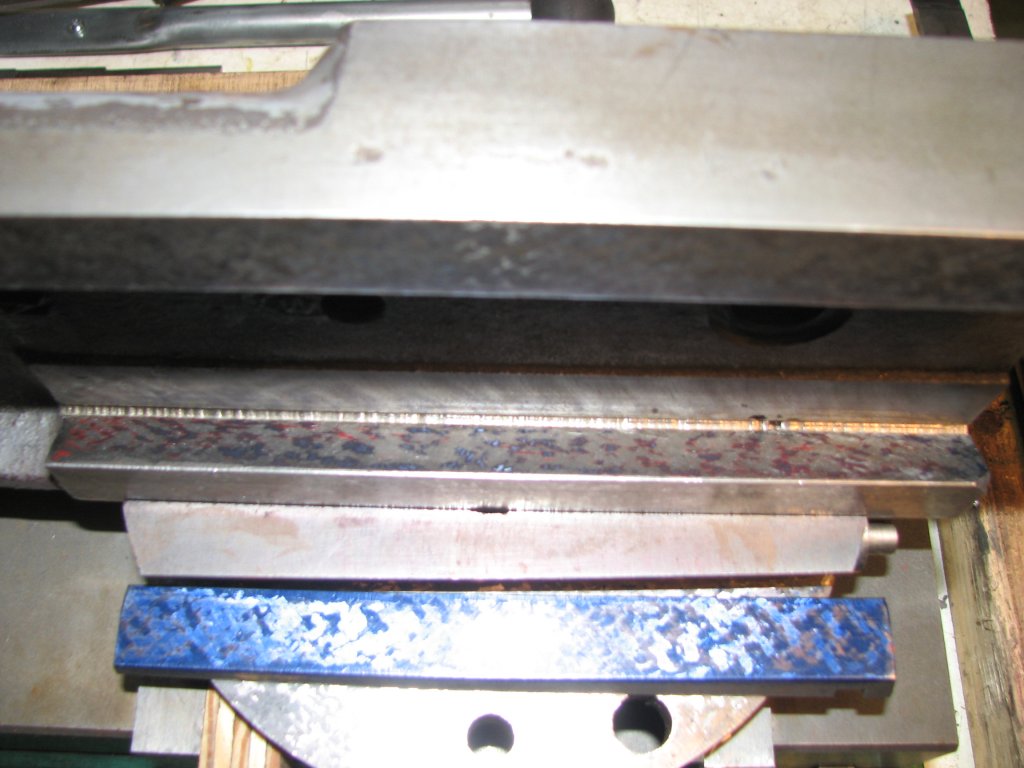
After a bit more scraping
using both a 55° template and the 60° ways on the tool head as
printing masters, I began to get coinciding prints on the angled
swivel block way. I printed with the template first using the red
Canode, then print over the top of it with the tool head inked in
Prussian blue. I was looking to see if the two prints matched each
other. This would indicate that the angle of the swivel block way
matches the angle of the tool head way and that the swivel block
way is as flat as the print from my template can show. I've found
that when printing with the Canode first, the red doesn't smear as
much as if I print red on top of blue. The fact that I am using a
55° template on a 60° angled way doesn't affect the prints. All I
need is for the angle of the template/straight edge to be less
than the 60° angle of the ways. I am using the 55° template
because it is thinner than my 45° straight edge and doesn't
overhang the angled way as far. I would prefer to use an even
thinner straight edge if I had one. The wider the surface is on
the printing master, the harder it is to keep it perfectly flat
on the thin surface that I am trying to mark.
|
|
| This
print was made with the angled straight edge. I will make
another print with the swivel block to check for the
proper angle. |
The
second print from the tool head ways shows that I have
matched the angle of the ways pretty closely.
|
Once I had both the two
prints matching each other pretty well and decent points per inch
showing on the swivel block ways, I installed the gib and measured
the gibbed way and scraped dovetail using the 1/2" shafts again.
The divergence between being parallel was now down to within a
tenth of so. It only took a couple hours a night for a week to get
this far on one way. I'd never make any money at being a machine
reconditioner, but it's a hobby, so making money is not the
object.
The next step was to measure the remaining tool head way that fits
with the tapered gib. I again set up the two 1/2" shafts and
extended the pins on my surface gauge to measure the divergence
from parallel. I had one tool head way that had been scraped and
one that had not. As I had expected, the outer ends of the angled
way were further away than the center. I would need to scrape the
center section of the way until it was the same distance from the
opposite way as the ends were. To double check my findings, I
installed the gib on the swivel block and slid the tool head on to
the ways. I then tightened the gib and slid the tool head to mark
the ways. I had color only in the center, but was impressed to see
that the center portion was marked over the entire width of the
way. It won't take as much scraping to get this way good bearing.
With all of the scraping I have done, the gib now doesn't have
much adjustment left. I had figured that this would happen. I've
gone from a gib that wasn't seating deep enough to a gib that was
seating too deep. Considering how much metal I have removed from
the flat and angled ways, this was no surprise. The more I scraped
off the flat ways, the larger the space became between the angled
ways. To compound the issue, I have also had to scrape the angled
ways and the gib. My plan at this point is to finish scraping the
one remaining angled way and see if I have enough gib adjustment
to get the tool head to fit with a small amount of clearance on to
the swivel block. If not, I will shim the gib with some long
feeler gauge stock to get the proper clearance. Once I determine
the proper thickness of the gib, I will machine and scrape in a
new one. I've done this on my import miller with good results. I
do find it somewhat amusing that I started with a gib that was not
seating deep enough into the dovetails and now have to build it up
to get it to seat properly.

|
|
| Measuring
between shafts to make sure that the ways are equidistant
from each other. |
The
side of the tool head that the gib rides against is
starting to show some even color.
|
I finished up
scraping the last angled way on the tool head. Printing the gibbed
side angled way was more time consuming than the opposite side as
I needed to print from my straight edge in red, then assemble the
swivel block with the gib inked in blue to make another print on
top of the red. Once I got the spots to coincide on the two
prints, I could then start refining the surface for better
bearing. The picture below left was when I had finally got the two
prints to pretty much match up. After another few passes, I had
enough bearing points. By this time, I had no adjustment remaining
on the gib and was using a five thousandths thick feeler on the
back side of the gib to get enough thickness to lock up the gib.
I again measured the divergence between the two angled ways as
shown above. This time there was next to no movement on the DTI
dial. The tool head and swivel block were finally finished. On to
the next concern. I have been thinking about the lock not working
while I have been scraping. I posted a question about it on the
Yahoo Metal Shaper group and received some mixed views about
whether my last resort of tapping the tool head for a locking
screw would be a good idea. My first choice has always been to try
and get the lock working as it was designed before I attempt to
modify the tool head lock.
I think that my best chance of getting the lock working would be
to provide a new surface on the tip of the locking screw. Since
there is also a slight depression on the side of the tool head
where the screw contacts, I have also decided that I would like to
put a new surface on the side of the tool head. Since I found that
the machined sides of the tool head were parallel with the center
line of the angled ways, I will be able to come up with a fixture
to set up the tool head on my surface grinder and clean up the
sides of the tool head. I will also take a skim cut off the top of
the tool head to get rid of the battle scars around where the
clapper box attaches to the face of the tool head.

|

|
| Printing
with the swivel block and gib shows that the angle is
correct. I am almost finished scraping the tool head and
swivel block. |
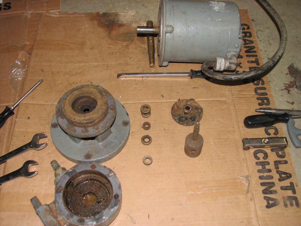
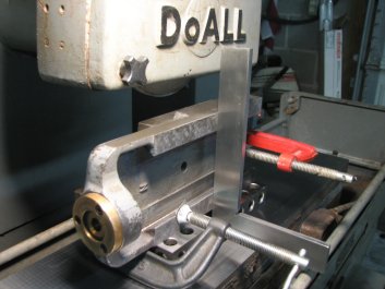
Always
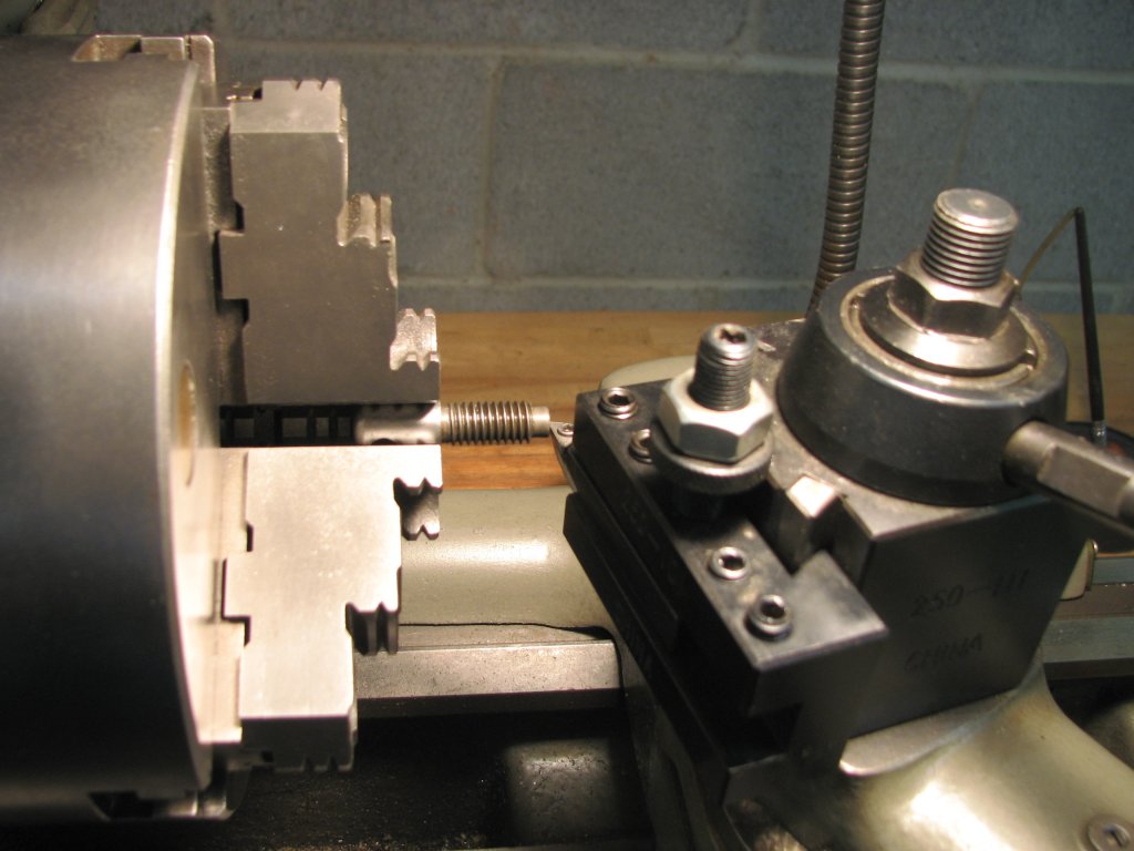
something. The coolant pump sprung a leak. I stripped
down the pump to find that the roto flex seal had self
destructed.
|
I had not used
my surface grinder much in the past year and have neglected the
coolant. I set up a cast iron block to do some test grinds
before I started work on the tool head. About half way through
grinding a 4" x 6" block, the coolant pump sprang a leak. It has
always dripped a little from the impeller housing seal, but now
it was coming out in buckets. Always something to keep me on my
toes.
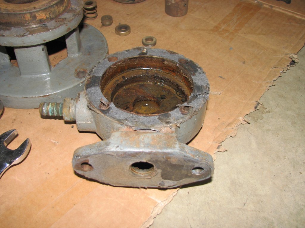
I stopped grinding and stripped down the pump. I thought that
the coolant I had chosen had rust
inhibitors, but from the look of the inside of the pump and the
bottom of the tank, apparently not enough of them. The pump
shaft seal was totally shot. My DoAll manual shows the part as
being a roto flex seal, part number 090-029307. DoAll's web page
shows the old part number as 90029307 with a new number of 2930.
Unfortunately they are out of stock. I gave DoAll a call and
found that their parts department uses another number, 002930,
and that they expected stock at the end of the month - a week
and a half away. I ordered the part, then cleaned up the pump
housing and tank.
I rigged up a old pump I had to supply coolant to the grinder
and got back to doing my test grind the next day. The part came
out nice and square, but has repeating patterns on the surface.
Not deep enough to measure with any tool I own, but not the kind
of surface finish I was proud of. The old belt that turns the
spindle has taken a set. Tuning the spindle by hand, I could
feel a good deal of resistance in one position. I ground a
couple more test pieces and switched wheels a few times. The
more I used the grinder, the better the surface became and the
less I felt the resistance from the belt set. The belt still
need to be changed, but the surface finish was now good enough
for me to continue with this project.

|
|
| Lots
of rust. I need to find a coolant that will withstand
extended periods of inactivity. |
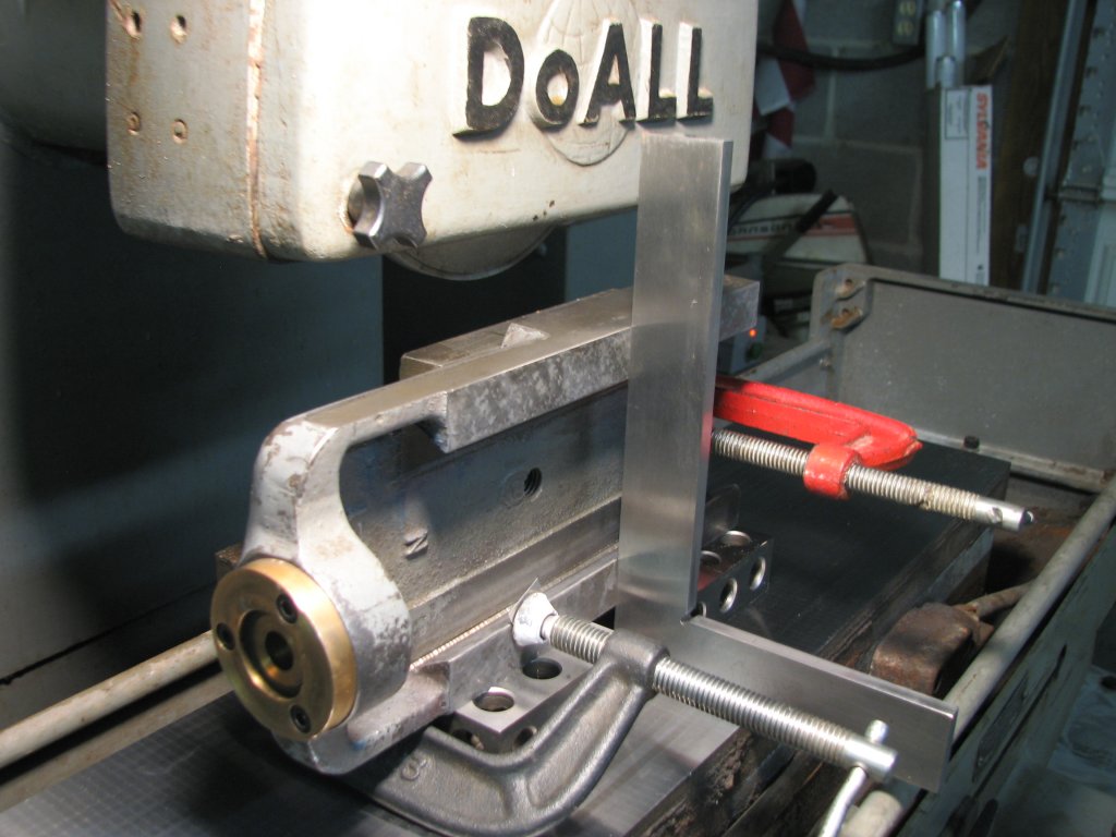
Setting
up the tool head on the grinder with a angle block and
1-2-3 blocks to keep the ways 90° with the magnetic
chuck.
|
I set the
tool head on the mag chuck and ground the top surface, then
checked it on the surface plate. The top surface and bottom
ways were true within a tenth and a half. When I checked the
sides of the tool head, they were out of square with the ways
and top surface by about a thousandth. I set the tool head up
on an 5" angle block with a couple 1-2-3 blocks under it and
clamped the tool head to the angle block. I checked the flat
ways and now found them square with the surface plate. I
transferred my setup to the mag chuck and again checked it for
squareness. I ground the one side, then flipped the tool head
over and ground the other side. I now had a tool head that was
square with itself.
The next issue to address was the tool lock. As I had said,
the 1/2" bolt that holds the lock body to the tool head
resides in a circular pocket. My thinnest walled 1/2" socket
didn't fit into the hole. On a chance, I tried a 13mm socket
and it fit with a tiny bit of clearance. I cleaned up the
mounting surface of the lock body and loosely attached it to
the swivel block. I assembled the tool head and tightened up
the gib so that it was locked up, then used some shim stock to
keep the distance between the lock body and tool head even. I
used some light duty thread locker on the bolt's threads and
tightened it up.

|

|
| I
found I had a 13mm socket that had thinner walls
than my 1/2". It took 0.012" in shims to prevent the
lock body from rotating during tightening. |
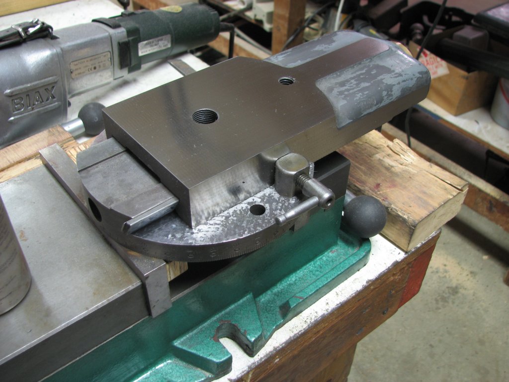
Test
fitting the lock screw after grinding the top and
both side surfaces. You can see the gib shim behind
the gib on the left side.
|
The last
step was to get rid of the slightly domed tip on the lock
screw. I removed the T handle from the screw and chucked the
screw up in the lathe and cut it square. I built a small jig
to hold the screw, then stoned the end of the screw to
improve the finish on its end. After reinstalling the screw,
it seems to be a lot better at locking the tool head.
I had cut a 0.007" thick shim to put behind the gib so that
I would have plenty of adjustment. While I will eventually
machine and scrape a new gib, I've decided to go ahead and
try the tool head out using the shimmed gib. I have used
some larger shim stock and was able to cut it to fit the gib
better than just using a feeler gauge. While I have made
gibs in the past that were not stress relieved, I would like
to stress relieve this one and that will require me to build
a heat treating oven. I've been thinking about building one
for a while and now have the reason and motivation to build
it. However, I want to finish the work on the shaper, so the
shimmed gib is going to stay that way for a while.

|
|
| I
turned the end of the screw square, then used a
fine stone to dress the end of the lock screw. |
The
tool head now seems to have much better gib
adjustment. The lock seems to fit better also.
|
I've also decided that I will paint the tool head before I
put it back on the shaper. While I hadn't planned on
repainting this machine, it seems a shame to spend all of
the time on scraping the tool head and leaving it with
peeling paint, so I now plan to paint the pieces I have
reconditioned. I like the darker gray that appears to be the
original color of this machine before it was painted over in
a lighter gray. Since I need to strip the old paint off the
tool head, it will take a week or so to complete. I will end
this installment by saying that I think that I have a pretty
good chance that the tool head will now lock and won't creep
down as it did before I reworked it. I am very pleased with
the feel of the tool head ways. It is a big improvement from
the way it was. The gib adjustment is now very smooth and I
am better able to regulate the tension supplied by the gib.
When I get the tool head back on the shaper, I will cut some
test blocks secured directly to the table, since the vise is
still in pieces. If I have stopped the creep, I will then
move on to scraping the table support and the boss it rides
on. Once that is complete, I will finally plane the vise
rails. I still have a fair amount of work to do, but I am
getting closer to completion.
©
Fager
September 28, 2015