
|

Sheldon 12"
Shaper - pg. 7
November 9, 2015 - December 4, 2015
After finishing
up on the scraping projects and now having the shaper able to turn
out more precise work, it was time to attend to a missing part. I
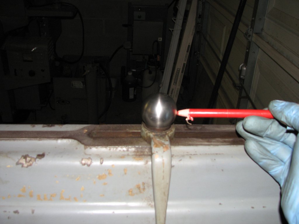
would attempt to recreate the missing ball handle that is used to
lock the length of the ram stroke. I posted a request asking for
the ball handle dimensions on the Yahoo Metal Shaper group. I
received them from a nice gent named Grant. The dimensions he gave
me were: 1.5" diameter for the bottom ball and 0.75" for the top
ball. He also said that the angle of the lever was approximately
15° and the length of the handle was about 3.75" between the ball
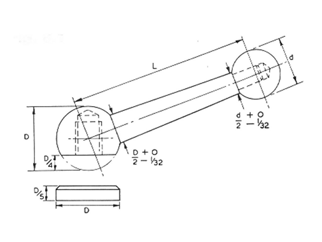
centers. The remainder of the dimensions were computed from the
picture (below left) also supplied by him. Doing the math, the
dimensions of the tapered shaft would be 0.719" for the large end
of the taper and 0.344" for the small end. I'll probably round
these up to 0.75" and 0.375". Grant wrote me that the ball handle
drawing and equations were attributed to British engineering
writer, George Thomas.
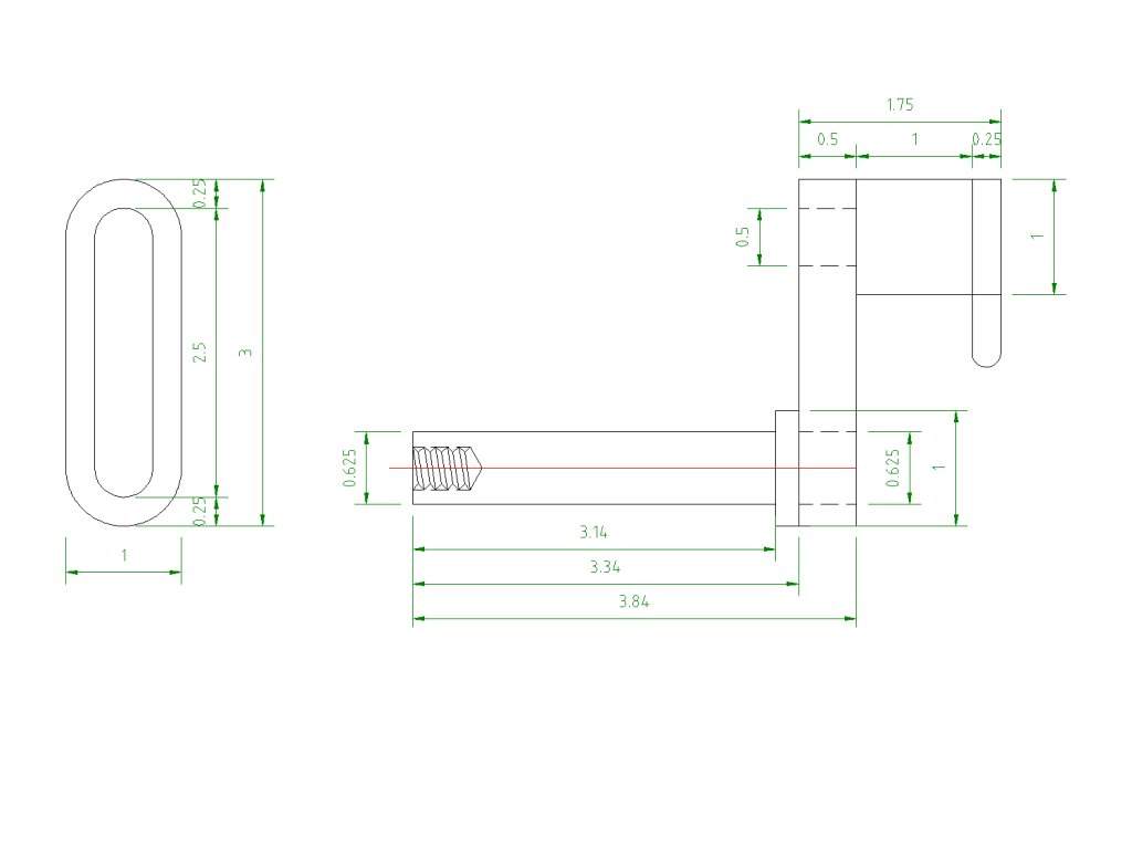
After getting
this information, I did a little more looking for info on ball
handles. I found another drawing here
that shows a different method to compute all of the necessary
measurements from the diameter of the larger ball. It doesn't
match exactly with the measurements I was given - the smaller ball
would end up as 1" rather than 3/4" - but the aesthetics of the
handle are as pleasing to the eye as the drawings I have made of
what I think the Sheldon ball handle looks like with the
dimensions I was given. After some thought, I figured that I would
go with the dimensions I received as my goal is to come close to
matching the original handle.
Since I didn't
have a radius turning attachment and have never turned a ball
larger than I could turn with a small form tool, I spent an couple
evenings looking at ball turner designs. I found that there are
two common types. Horizontal and vertical. The vertical type is
often referred to as being an "over-the-top" ball turner. Both
horizontal and vertical have their strong and weak points, but I
liked the simplicity of the vertical radius attachment. I
decided to go with an over-the-top design that would fit into my
quick change tool post boring bar holder. Both of my quick change
boring bar holders are 0.625" diameter. After some searching, I
found a design that I could modify to suit my purposes at homemetalshopclub.org
in their news letter: ball
turner - newsletter1004.pdf. With a picture to work from, it
was time to sketch out the dimensions and get started building it.
 |
 |
| Ball
handle design. |
Ball
turner plans. |
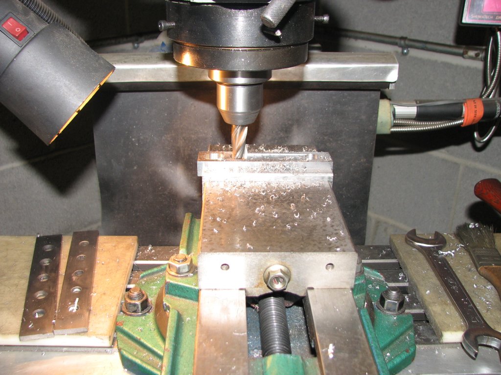
I got started
with building the ball turner by milling some 0.5" thick cast iron
to the shape of the arm. I milled the piece to 1" wide by 4" long,
then milled two slots centered on the width. One 0.5" X 0.625" and
another 0.5" X 2.75". The smaller slot is oval/oblong shaped
and I will duplicate the same shape on the pivot shaft so that the
arm and shaft will lock together and prevent the arm from rotating
on the shaft. The larger slot will allow the tool bit to have an
adjustment range of 2.25". I figured that this would give me
the capability of turning about a 4" ball. Once I machined
the parts and tried to set it up on the lathe, I found that I
hadn't thought the changes to the original design through well
enough. With one end of the arm locked to the pivot shaft, the
adjustment that set the size of the ball was on the wrong end.
With the arm fixed at the pivot shaft, unless I turned a ball at
the maximum diameter, the arm would overhang the tool holder and
would be the closest point to the lathe chuck. This wouldn't do. I
ended up having to cut the arm down and remove the end that
attached to the pivot, but I will cover that a little later.
 |
 |
| Machining the arm for the turning tool out of 1/2" thick cast iron. | Turning the shaft that fits into the arm. This was turned to 5/8". Two flats will be milled to produce a 1/2" X 5/8" oval, so it will lock into the arm. |
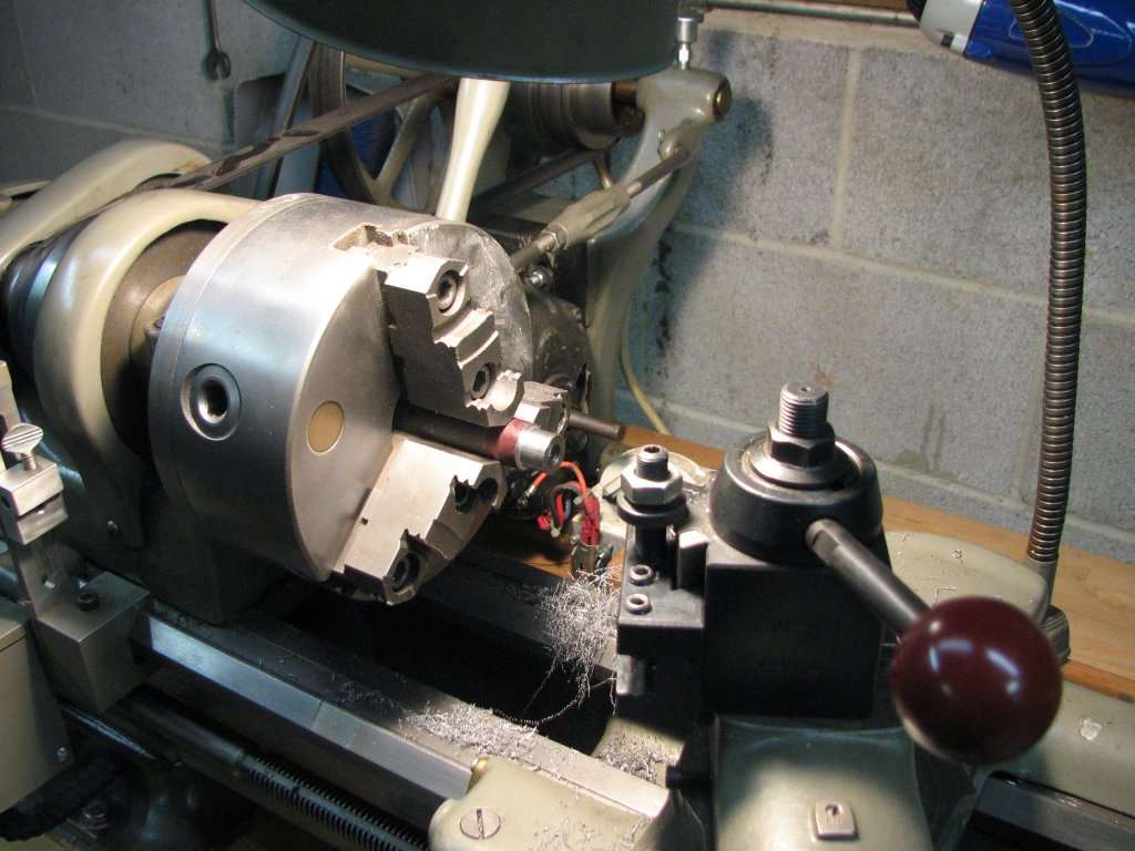
With the arm
machined and waiting on radiusing the ends on the miller, I moved
on to the pivot shaft that would fit into the boring bar holder.
While I designed the shaft to be turned from 1" stock, I ended up
using 3/4" A36 steel bar. The shaft will be turned to 5/8" and a
0.25" section will be left at 3/4" to act as a shoulder to
position the shaft in the holder. The length of the pivot shaft
portion is 0.20" longer than the boring bar holder. I will machine
a 0.199" spacer to give 0.001" axial clearance so that the shaft
will rotate without excessive end play.
While turning
the piece on the lathe, I was getting a little chatter even though
my bit was sharp and positioned correctly and all of the slides
were locked. After I finished the shaft, I discovered that I had
neglected to tighten the spindle locking nut's set screw firmly
after I snugged up the lathe's end play needle bearings. The nut
had loosened up and the excessive end play had caused the chatter.
I had removed the bearings to inspect them a couple days previous
and must have gotten side-tracked during the adjustment. With the
bearings snugged and the set screw for the nut tightened firmly,
the chatter went away and the decent finish returned on the next
part I turned.
 |
 |
| Blurry
pic of turning the shaft that fits into the boring bar
holder. Each end is tapped 3/8"-16. I used a live center for additional support. |
Test fitting the boring bar holder on to the shaft. I chose a very close slip fit. As it wears, I can tighten the holder to compensate for wear. |
I had made a
change to the original plans and had increased the length of the
top cylinder that acts as the tool bit holder so I could turn
larger balls. I turned the overall length to 3" and turned a 1/2"
diameter section a little less than 1/2" long to fit into the arm.
Once I did a test fit-up on the lathe, I realized that I had made
the tool holder section too long. I chucked it back up and
shortened the overall length to 1.75". The shorter tool holder
would allow me to not need to have the cross slide at its
retracted limits. The shorter tool holder should also help keep
the ball turner a little more rigid.
 |
 |
| Before tapping the tool bit holder, I had milled, drilled, and tapped for the tool holder set screws. I started the tap on the lathe and finished tapping it on the bench. | Milling
the radiused ends on the arm that goes between the pivot
shaft and tool holder. The arm is bolted to a MT2 taper
and secured with hold down clamps. |
As I said
before, I had initially cut a 0.5" wide, 2.75" long slot and
a smaller 0.5" wide, 0.625" long second slot in the 4" arm. The
second smaller slot was planned to fit on a similarly shaped
protrusion at the end of the pivot shaft. The shaft had been
turned to 0.625", then I cut small 0.0625" deep flats on either
side and filed each end's half-circular diameter from 0.625" to
0.5" to produce an oblong shape which fit into the slot. This
would keep the arm from turning on the shaft. I thought the second
slot would be a good idea, however I encountered a problem with my
changes to the original design.
While doing the test fit, I discovered that why a second shorter slot wasn't a good idea. The shorter oblong slot I had machined introduced a problem with setting the position of the tool holder. The tool holder's position could only be set from the end of the arm closest to the tool holder. I surmised that when turning smaller balls, the arm would overhang the tool holder. That meant that the arm would be the closest point to the chuck and that the stock I was cutting the ball from would have to stick out farther from the chuck than necessary. Not good for trying to keep things rigid.
 |
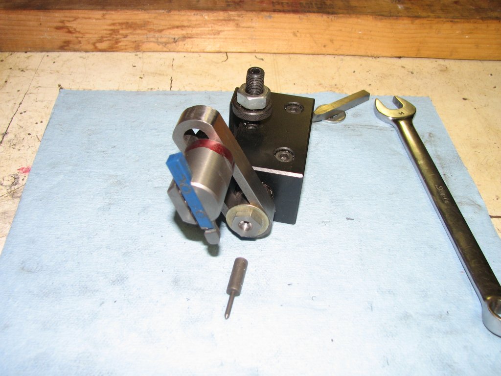 |
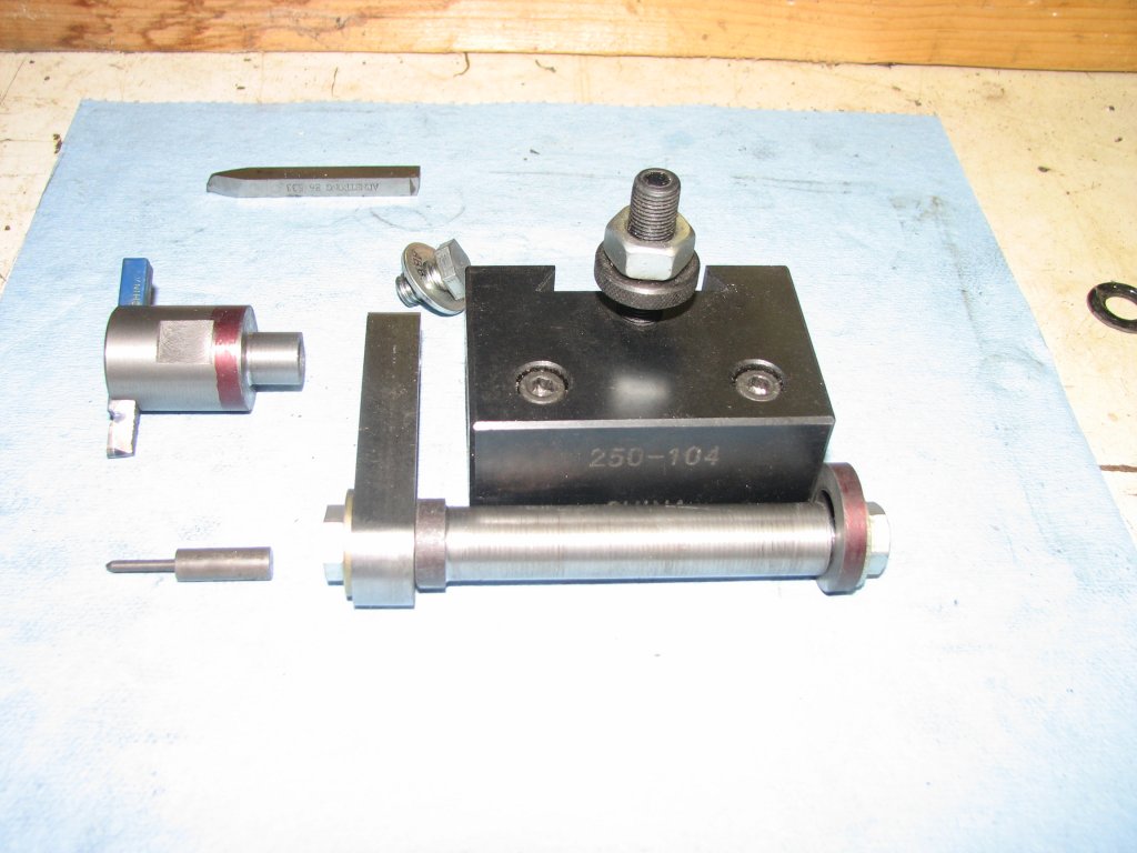
| The
parts are ready to assemble. A couple flats were cut on
the tool holder so that I could hold on to it with a
wrench. |
Front view of the assembled turner. The small cylinder with point fits into the pivot shaft and is supposed to help setting the height of the turner. |
I decided to remove the second hole from the arm so that setting the distance of the tool bit to pivot shaft (which sets the ball diameter) would be made on the end that attaches to the pivot shaft. The arm now looks like a block letter capital 0 - as shown in the plans in the second picture at the top of the page. This allows for no overhang of the arm on the tool holder end. The picture (below right) shows the type of overhang that I didn't want. The oblong shaped portion of the pivot shaft still prevents the arm from rotating and I think this is a good upgrade to the original design. I used my rotary table on the miller to radius each end of the arm. The radiused ends will allow the tool holder to be used closer to the lathe chuck. Since the tool holder is not restrained from rotating like the pivot shaft, I will be able to position the tool holder and bit to cut as close to the chuck is possible. The less the work sticks out from the chuck, the less chance of chatter when turning the ball. The South Bend 9" lathe is not known to be the most rigid of machines, so anything I can do to limit potential chatter is helpful.
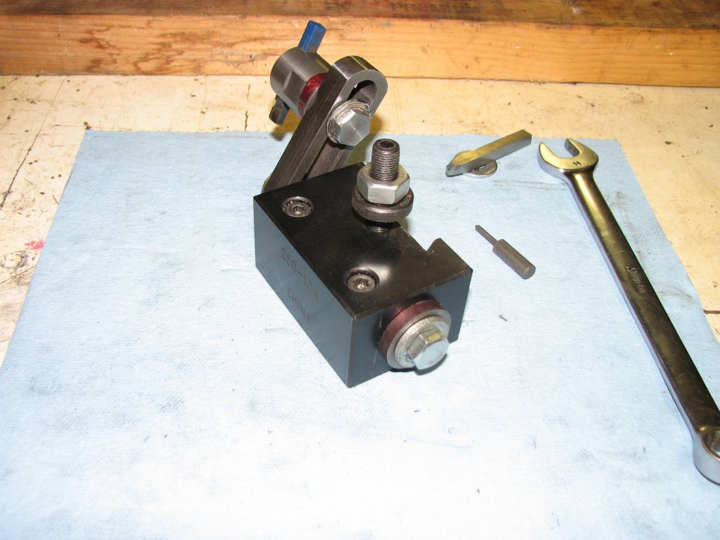 |
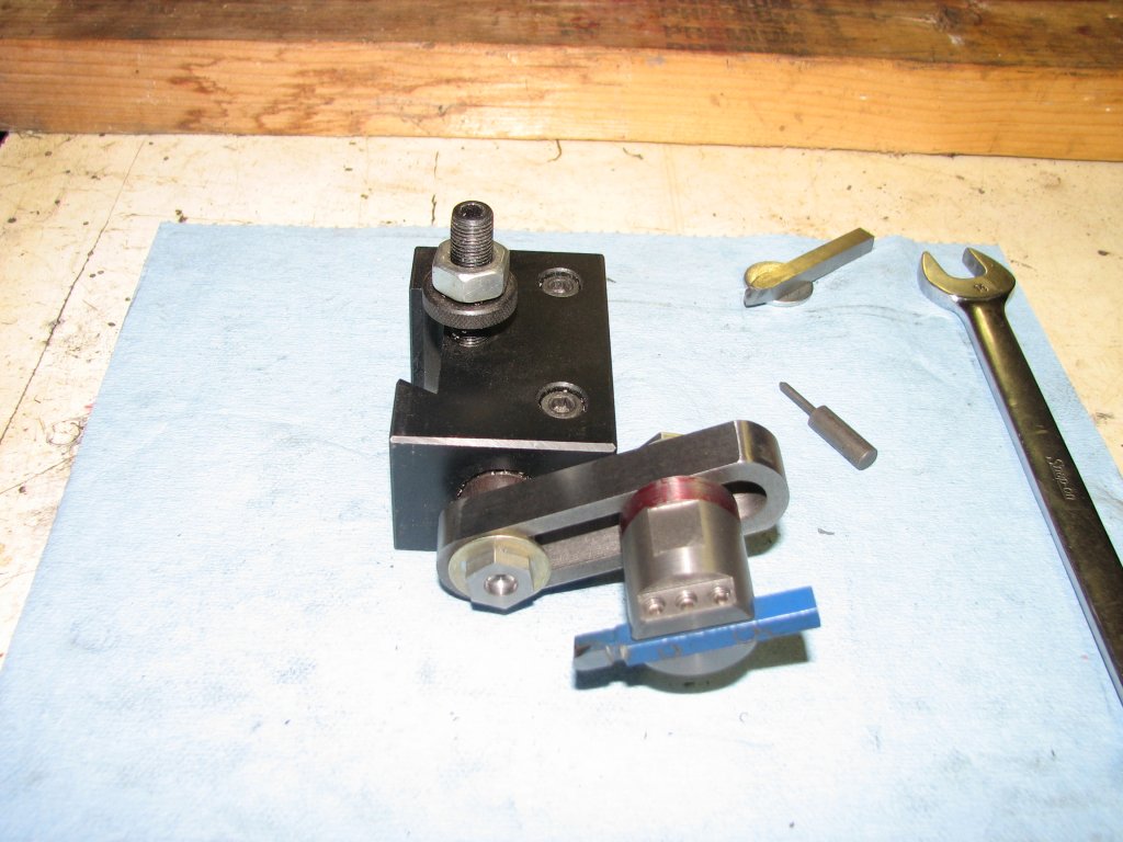 |
| Rear
view. With the bolt tightened, there is a thousandth end
play in the pivot shaft. The ball turner is moved by a
wrench. |
One more front view to show the set screws that hold the tool bit in place. I plan to try a few different grinds on the tool bits. |
Through a nice
design to work from and some trial and error, I ended up with what
I thought would be a workable ball turner. The original plans had
also included a pin that was to be used as a pointer to help
setting the center of the pivot shaft on the center of the work.
When I tried the ball turner out on a piece 3/4" of stock, I found
that the pointer didn't work well enough for me to accurately set
the pivot shaft at the work's center point. If the pivot shaft is
set too high, the center of the cylindrical stock (largest
diameter of the ball) will turn out taller than the ball is wide.
If the center point is too low you end up with a football shape
instead of a sphere. Fortunately with a vertical ball turner,
there's another way to set the pivot shaft on center. I centered
the shaft roughly by eye, touching it to the end of the bar stock.
I then set the tool bit to just touch the top of the work. I then
moved the carriage toward the tail stock, placed the tool bit
under the work and moved the carriage back into position. There
was now a gap between the tool bit and work, this meant that the
ball turner pivot shaft was too low. I placed a feeler gauge
between the tool bit and work to measure the clearance, then moved
the quick change tool holder up half the distance of the thickness
of the feeler gauge and had the pivot shaft perfectly aligned in
height. I reset the tool bit to just touch the top of the work and
was ready to set the lathe's Y axis (cross slide in and out).
The tool bit
also needs to be set directly on center in the Y axis. I placed a
dead center in the tail stock and lined up the tool bit with the
point of the dead center. I was ready to try and turn a ball. The
first ball I turned was not a perfect sphere, but pretty close. I
was out less than 0.010" from the ball being perfectly round. My
error was a bump on the chuck side of the ball. This was due to
the tool bit holder touching the bar stock on the chuck side of
the ball and lifting the tool bit. I needed to angle the tool bit
so that the tool holder doesn't rub. I'm confident that with
another couple of practice cuts, I can get the balls closer to
spherical.
 |
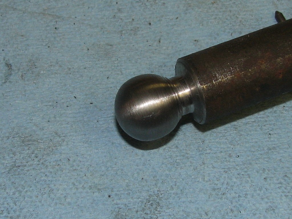 |
| The
first test ball. I am using a tool bit that was ground to
a 60° included angle (like for threading) with about 8°
back rake and 10° side rake. |
Not
perfect, but not too bad for the first attempt. Hopefully with some practice, I should be able to do a bit better with the concentricity. |
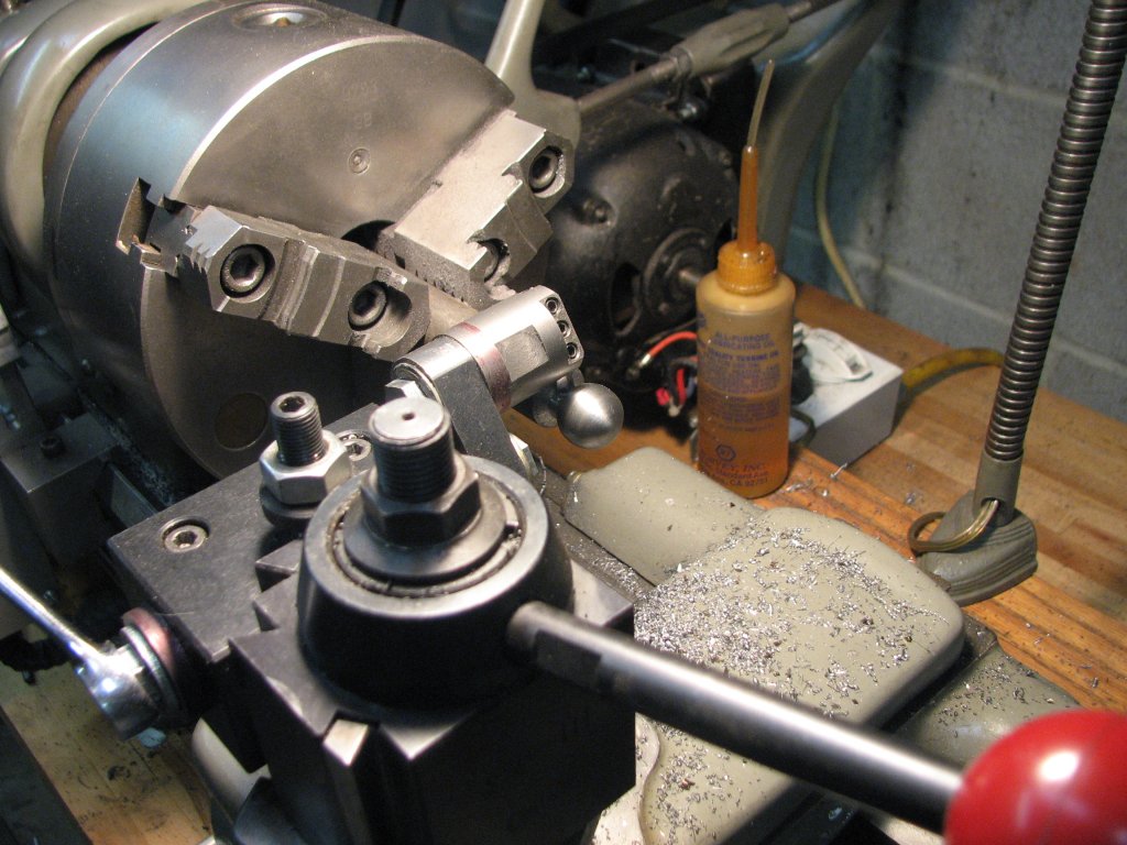
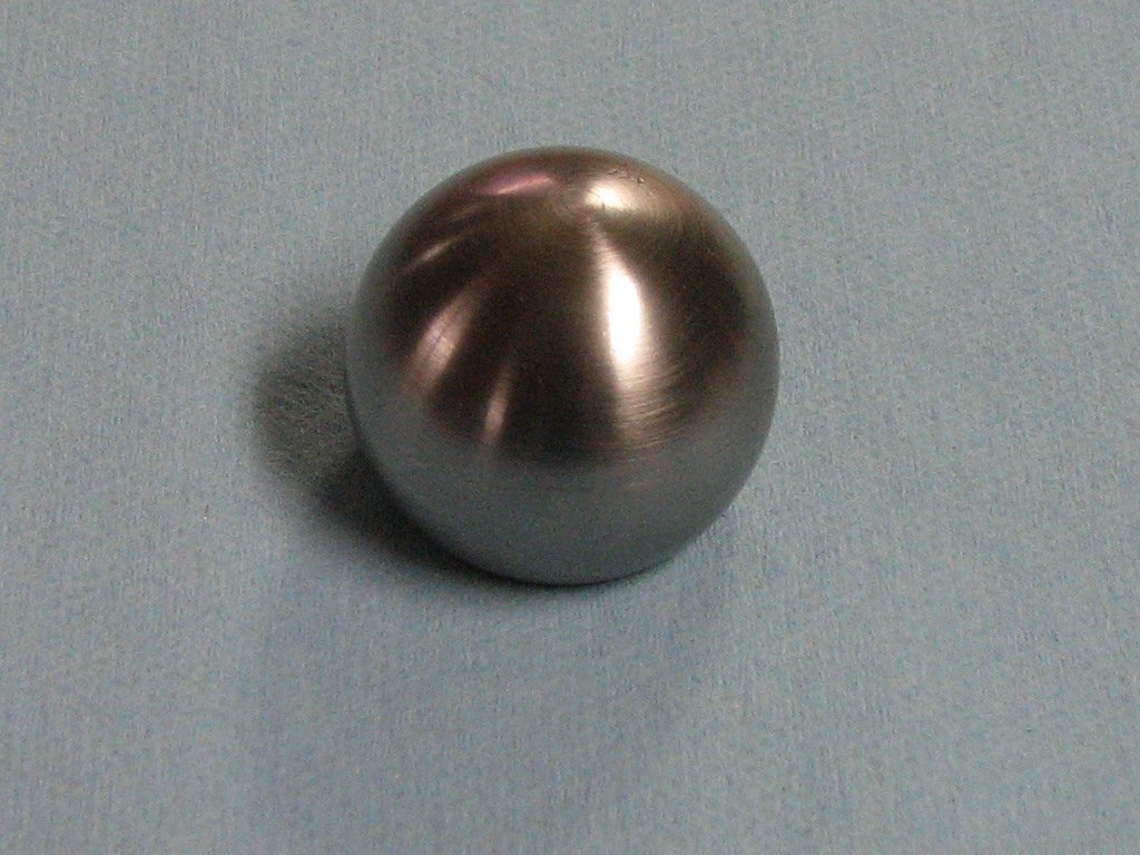
I cut one more
test ball using 3/4" stock with the tool bit angled so that the
tool holder wouldn't hit the chuck side of the stock. This time
the ball came out concentric. It had a pretty nice finish as well.
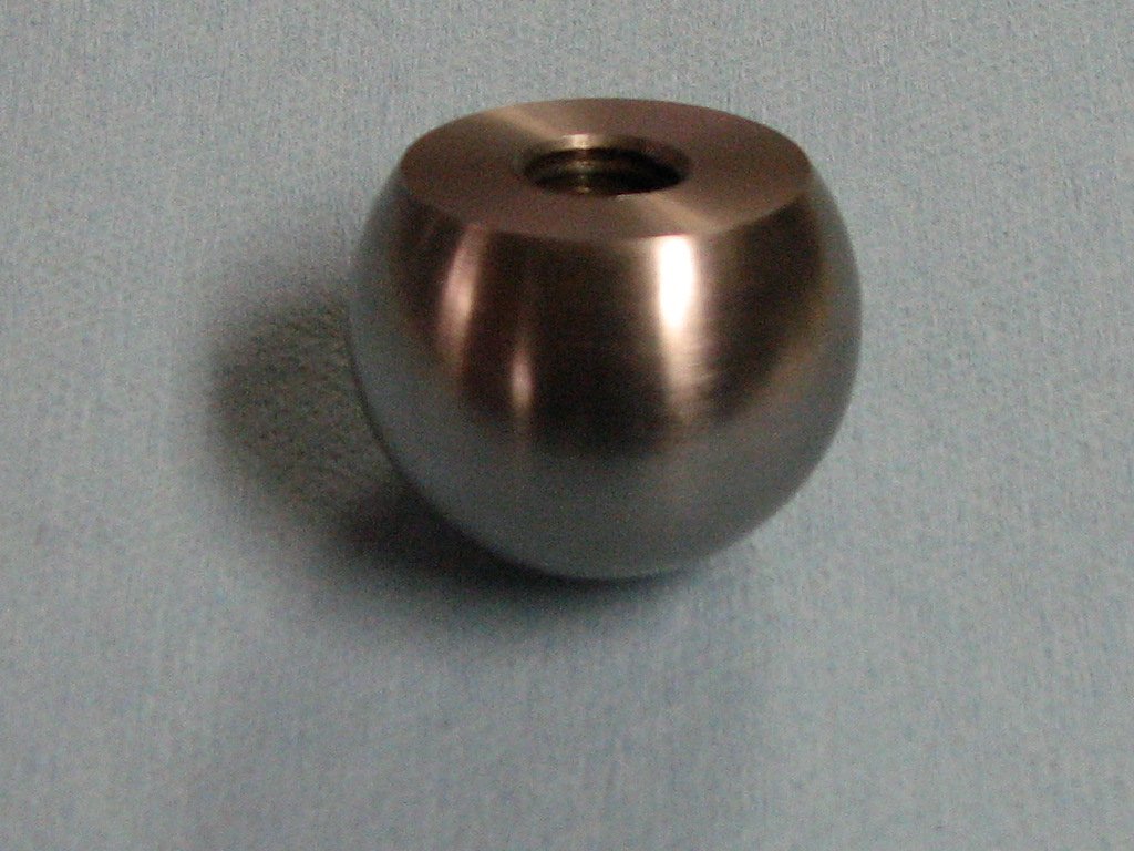
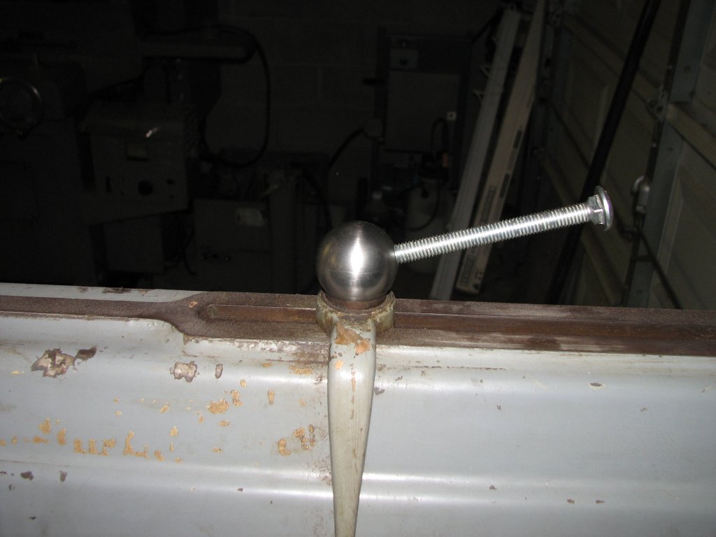
It was time to try a 1-1/2" ball for the lower ball of my handle.
Most of the examples I had seen written about had turned the larger ball and the tapered shaft as one piece. I thought that the transition between the ball and tapered shaft looked very good on these examples, but I didn't like the fact that the lathe-turned finish (concentric rings) of the larger bottom ball was aligned with the angled handle. It just didn't look right to me. I would prefer that the larger ball to be turned so that the finish was horizontal and thus parallel with the top of the shaper's ram. If I could finish the ball so that there was no visual evidence of which axis that I turned it on, it wouldn't matter, but this wasn't the case. This was one of those times where the look of the part was more important to me than the ease of producing it. My choice did make assembling the ball handle a little more work, but after looking at the finished handle, I thought that it was worth it.
 |
 |
| Using
some ABS tube to keep from marking the ball, I cleaned up
the flat surface and tapped for 1/2"-13 threads. |
The larger (bottom) ball turned out pretty nice. As with most of my projects, a bit of practice is required before I get decent results. |
I turned the ball from some O1 steel, then parted it off so that the parting line left a little more than 3/4 the diameter of the ball. I was pleased with the finish I got on the ball. I re-chucked the ball using a plastic sleeve so as to not mar the surface, and took a light facing cut to put a nice finish on the bottom surface. I then drilled and tapped for 1/2" -13 threads that were 1.10" deep using a taper tap, then a bottoming tap. I started the tap on the lathe to make sure that it was square with the hole, then moved it to the bench vise and finished the tapping. The stud on the ram is a little less than inch tall and tapping to 1.10" gave me some extra thread depth. I now needed to sink another hole with threads at a 15° angle to the bottom flat on the ball. I wanted the handle to align with the shaper's ram center axis when tightened, so I screwed the ball tightly on the stud and marked the ball at the rear so that it aligned with the center-line of the ram. I thought that the ball handle would look better if it didn't stick out to either side when it was tightened. If I was going to take the time to make this handle, I wanted it to look like it was engineered for the shaper.
Since I had a
half inch hole in the center of a 1.5" diameter ball, the thread
depth on this new 15° hole could only extend a little less than
1/2" before hitting the threads I had cut. If I drilled the second
hole not to interfere with the first, my thread depth would barely
reach deep enough to securely attach the handle. I decided to
drill the 15° hole through the threads I had already tapped. This
would allow me to tap the new 3/8"-16 threads right up to the
1/2"-13 threads. Yes, it would weaken the 1/2"-13 threads a bit,
but there's more than enough thread depth on the 1/2" hole, so I
didn't think that it would be an issue. Once I had the 3/8"-16
threads tapped, I ran the 1/2" tap back down the center hole to
clean the previous threads up. The large ball was finished and I
was pleased with the way it looked. It was now time to move on to
turning the tapered handle and smaller ball.
 |
 |
| Underside
of the ball. The flat and threads turned out as planned
and I am now ready to drill and tap for the handle hole at
15°. |
Marking the ball so that I can drill and tap for the tapered handle. I want the handle to align at the position shown when it's tightened. |
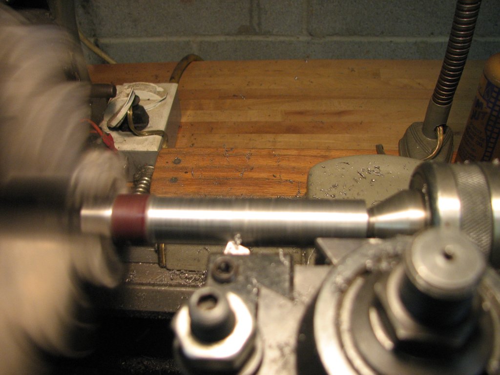
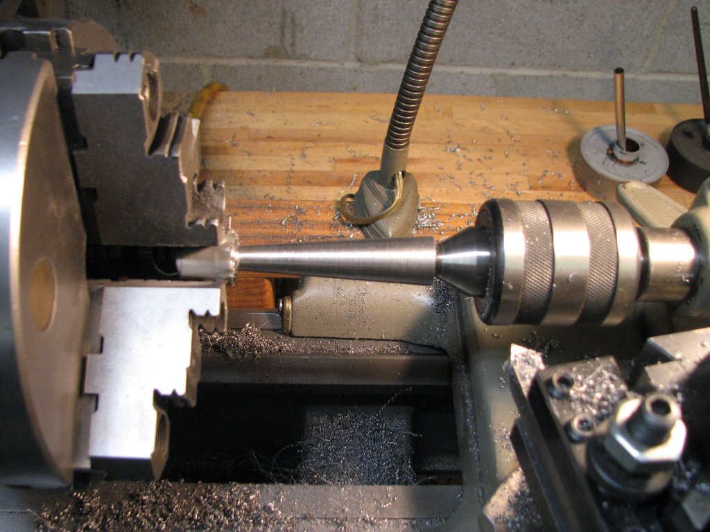
To make the
small ball and attached tapered shaft, I used A36 - 3/4" round
stock. To get the ball concentric, I needed to turn it to 0.745".
In order to turn the taper with the compound slide, the angle of
the slide needed to be set so the shaft's diameters would be 3/8"
on the small end and 3/4" on the large end over a center line
length of 2.625". This worked out to needing to set the compound
slide to 4.086° from the center line of the shaft. This kind of
accuracy wasn't going to happen by using the compound slide's one
degree angle resolution increments, so I used a dial protractor
held up against a precision bar held between centers to set the
angle. After a couple attempts, I got the compound slide set close
enough to suit me. Before I turned the taper, I drilled and tapped
the end opposite the ball for 3/8"-16 threads. I would use a piece
of threaded rod to attach the handle to the larger ball. Since I
only had about a 1/2" of 3/8"-16 threads on the large ball, I
didn't make a flat on the larger ball where the handle would
attach. I figured that the more threads I could engage, the
better. To get the handle to fit snugly with the ball and not show
a gap, I turned the end of the handle concave where it would
attach to the ball. In retrospect, it would have been a little
easier to have turned the larger ball and the tapered shaft as one
piece, but sometimes I make choices for artistic, rather than
practical matters. Hopefully the ball handle will turn out as I
envision it.
 |
 |
| After
drilling and tapping for 3/8"-16 threads, the carriage
bolt shows the position that the handle will assume when
tightened. |
I had to turn the tapered shaft in two setups due to the short length of travel on the compound slide. It came out fine in spite of the lathe's limitations. |
 |
 |
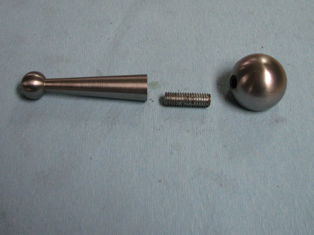
| The
three parts that make up the handle. If I make more
handles, I will have the taper attached to the larger
ball, but I'm pleased with the results. |
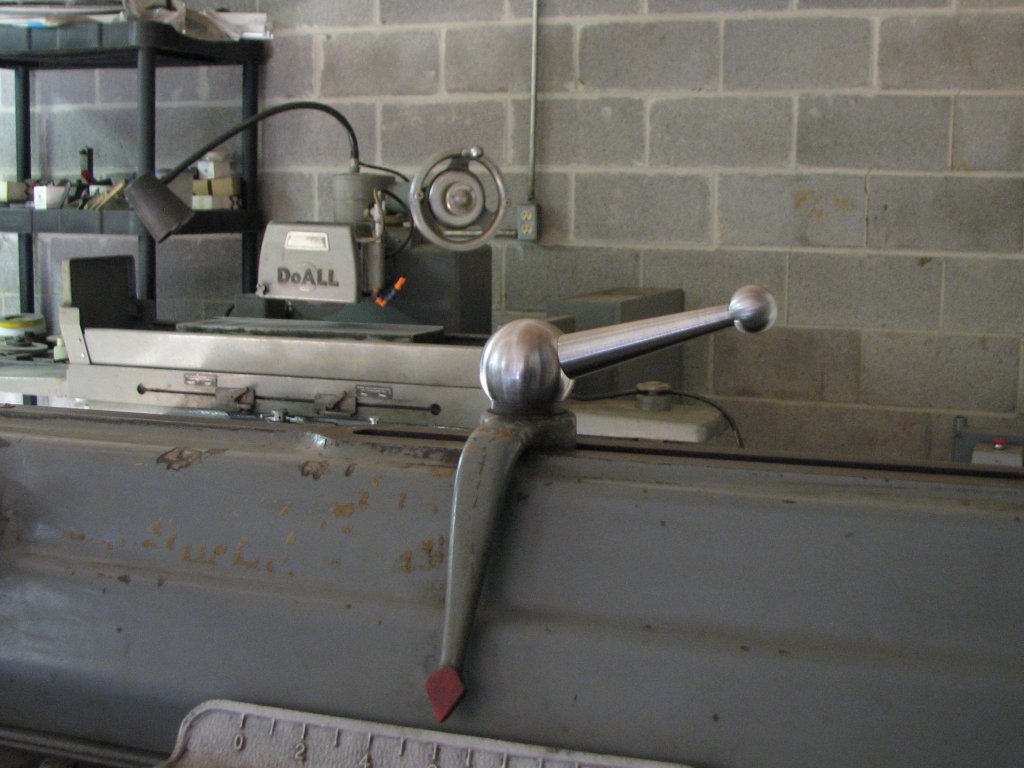
The handle looks good on the shaper. A lot better than the single nut that was on the stud when I got it. I am now thinking that I need more ball handles. |
The project is
finished and I am pleased with the results. I am now thinking
about adding some ball handles in place of the table support nuts
so that I don't need to grab a wrench each time I change the table
height. However, I first need to attach the shaper to the concrete
floor. I have been reading about different methods of attaching
studs or nuts to the floor and at this point, I am leaning toward
drilling holes in the concrete floor and using epoxy made for
anchoring studs in concrete. I think I want to use bar stock
tapped for internal threads and set them below the grade of the
floor so that if I want to move the shaper at some point in the
future, I won't have studs sticking out of the floor in that
location. I'll need to disconnect the wiring and its conduit to
move the shaper enough to drill the holes, so this won't be just a
few hours work, but it needs to be done. I don't want to be forced
to run the shaper at half speed or less due to it wanting to walk
across the floor at higher speeds.
| Shaper 1 |
Shaper 2 |
Shaper 3 |
Shaper 4 |
Shaper 5 |
Shaper 6 |
Shaper 7 |
Shaper 8 |
Shaper
9 |
© Fager December 4, 2015