
|


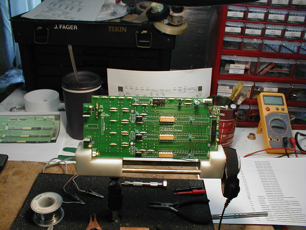 The circuit board is partially assembled. |
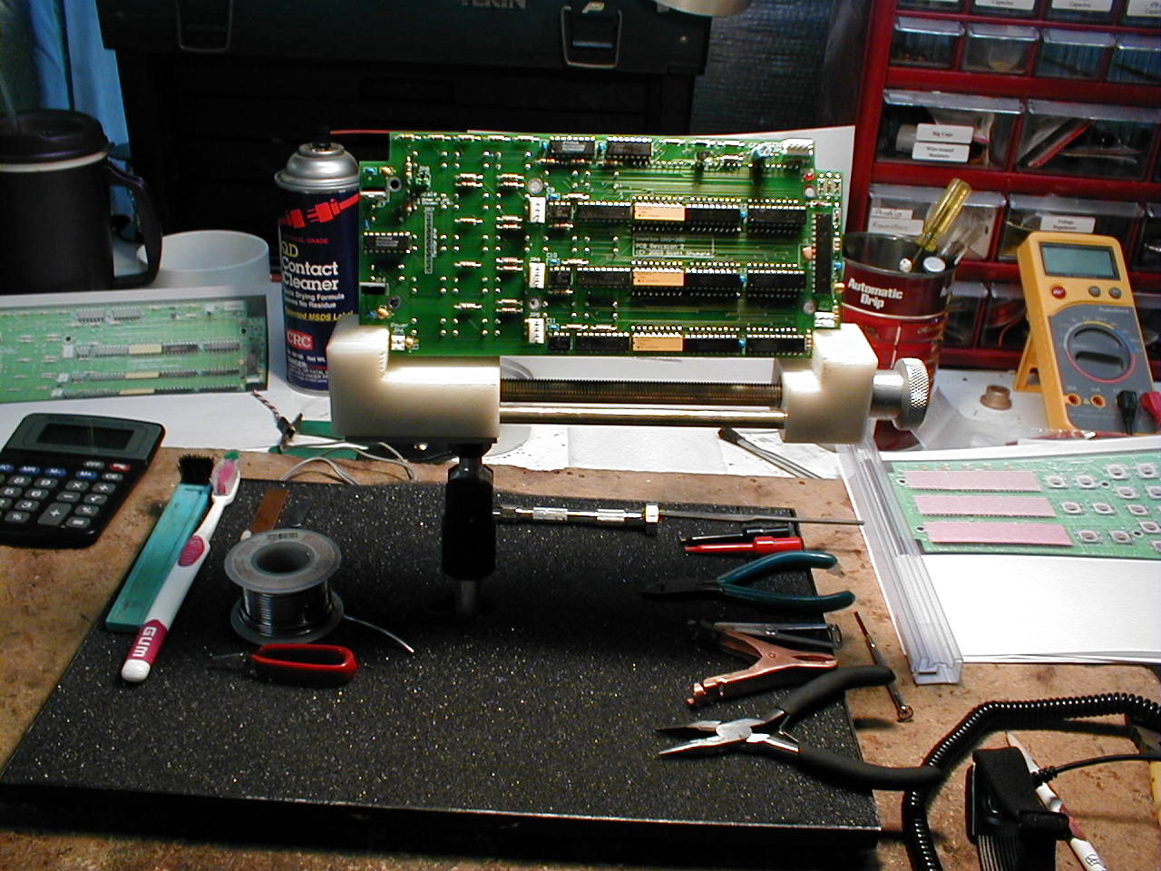 |
| The
remainder of the ICs get installed. |
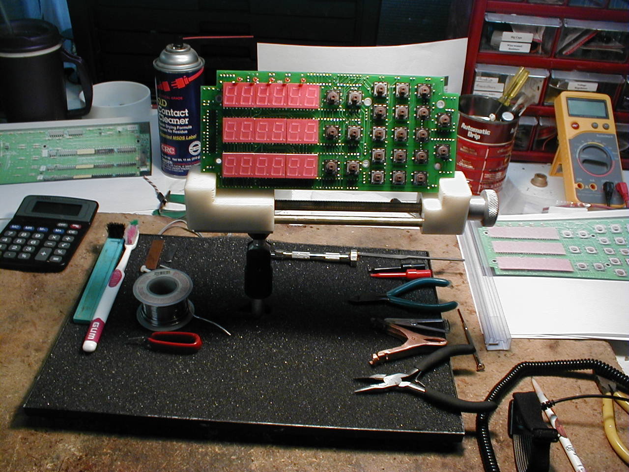 |
| The
tactile switches and displays are installed. |
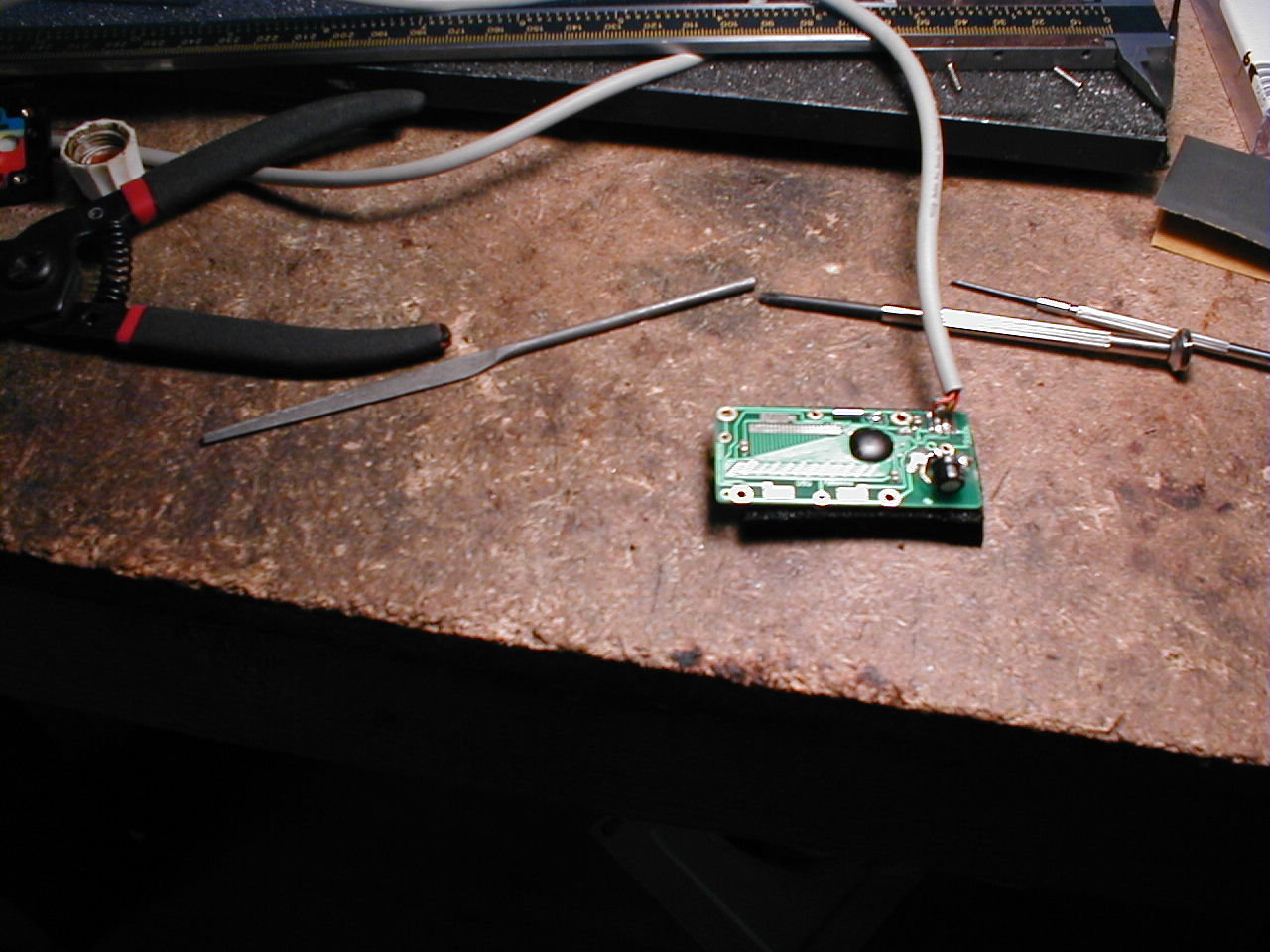 |
| Soldering
a cable to a Harbor Freight digital caliper. |
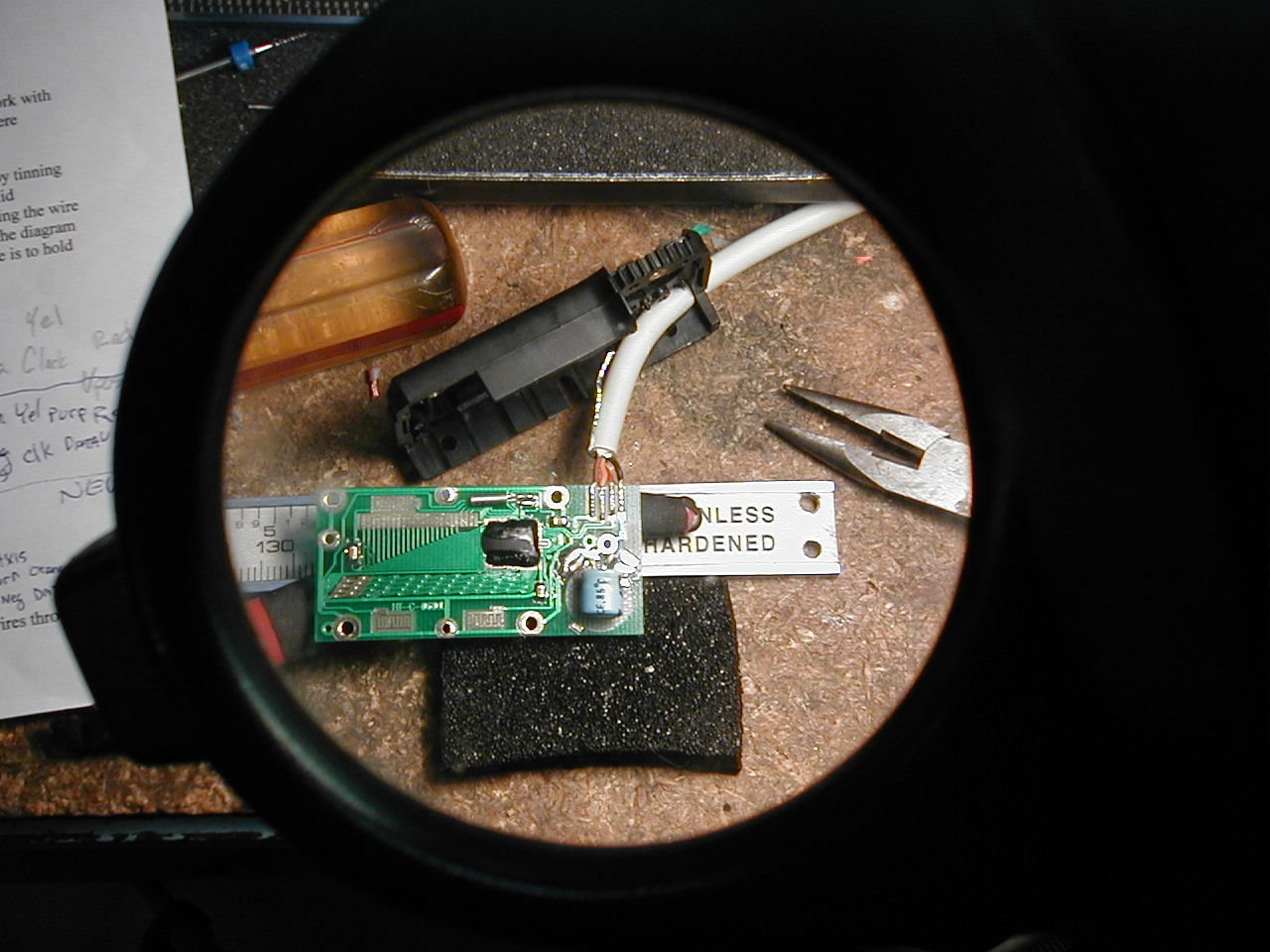 |
| A
close-up of the same. A 100µF electrolytic capacitor is
substituted for the standard button type battery. |
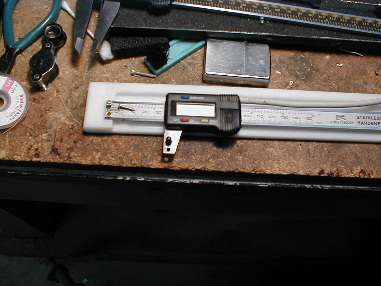 |
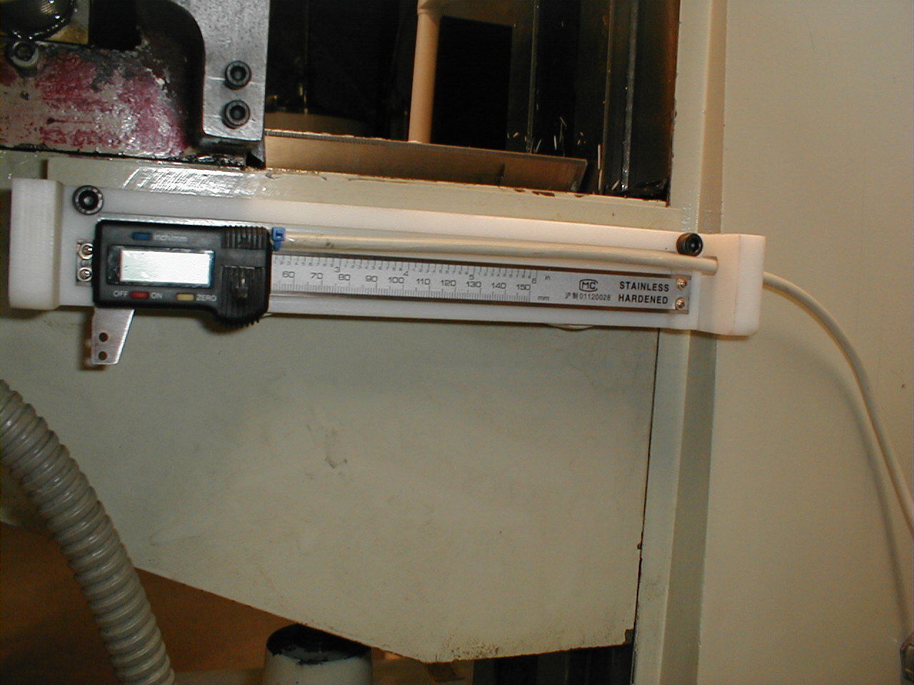
| With
3-1/2 of the 4 caliper jaws removed, the caliper is transformed into a
digital scale and mounted. |
 |
| Holes
are drilled free-hand in the saddle. It appears that before it
was beige, the saddle was painted red! Well, at least the other
side is beige. |
 |
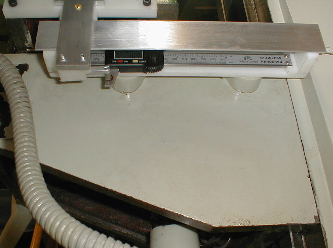
| The Y
axis scale is partially mounted. |
 |
| Control
arm and cover are installed. |
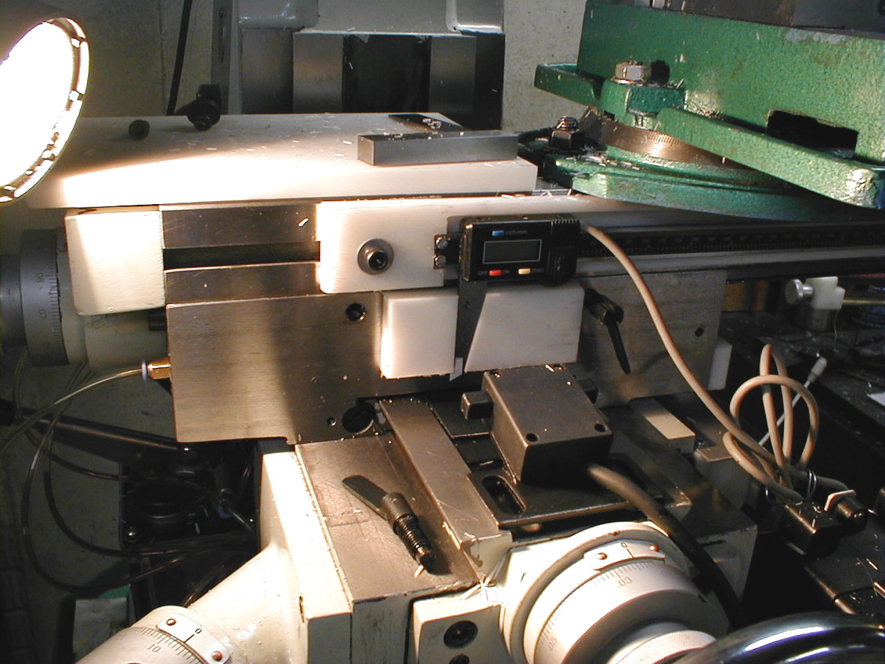 |
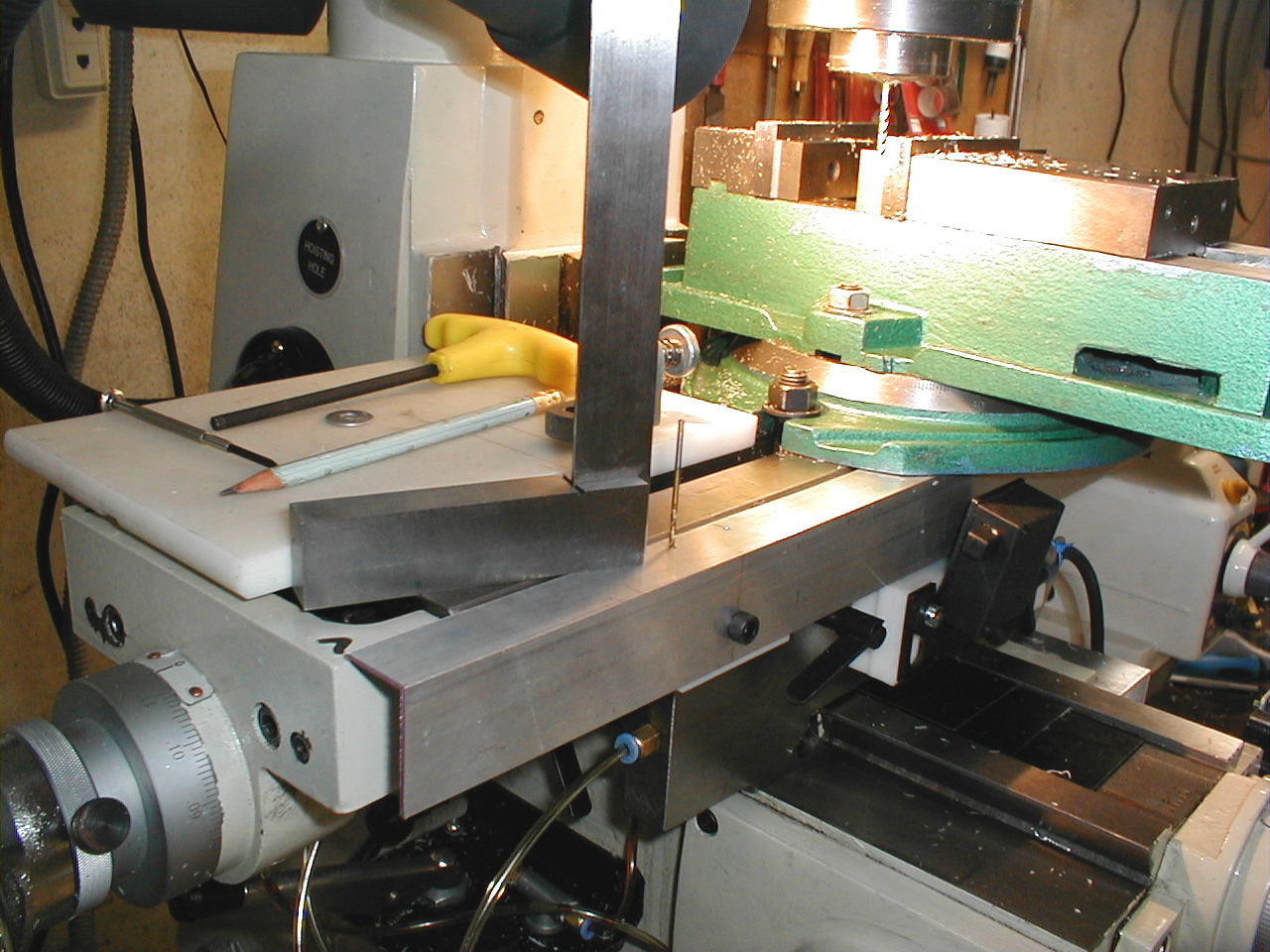
| Working
on the X axis. This is a temporary scale that will be used until
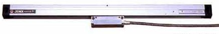
my new Jenix scale arrives. |
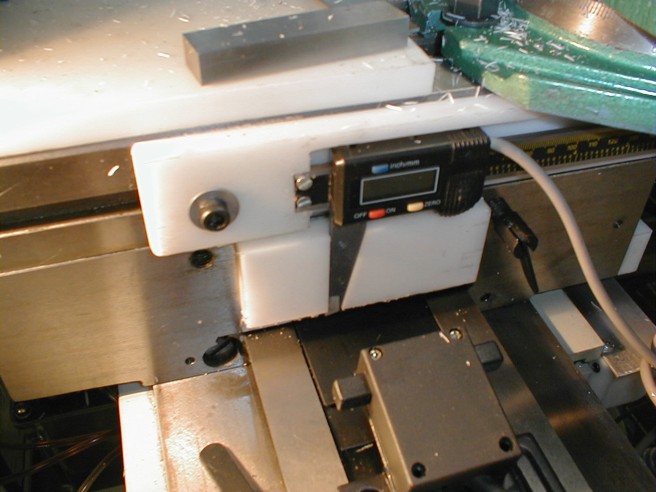 |
| The
caliper jaw is embedded into the plastic. Having this much
surface holding the jaw made for good support. |
 |
| Bolt
holes are added. |
 |
| Aligning
the holes for the cover. An extra drill bit holds the cover in
place while I measure for the next hole. |
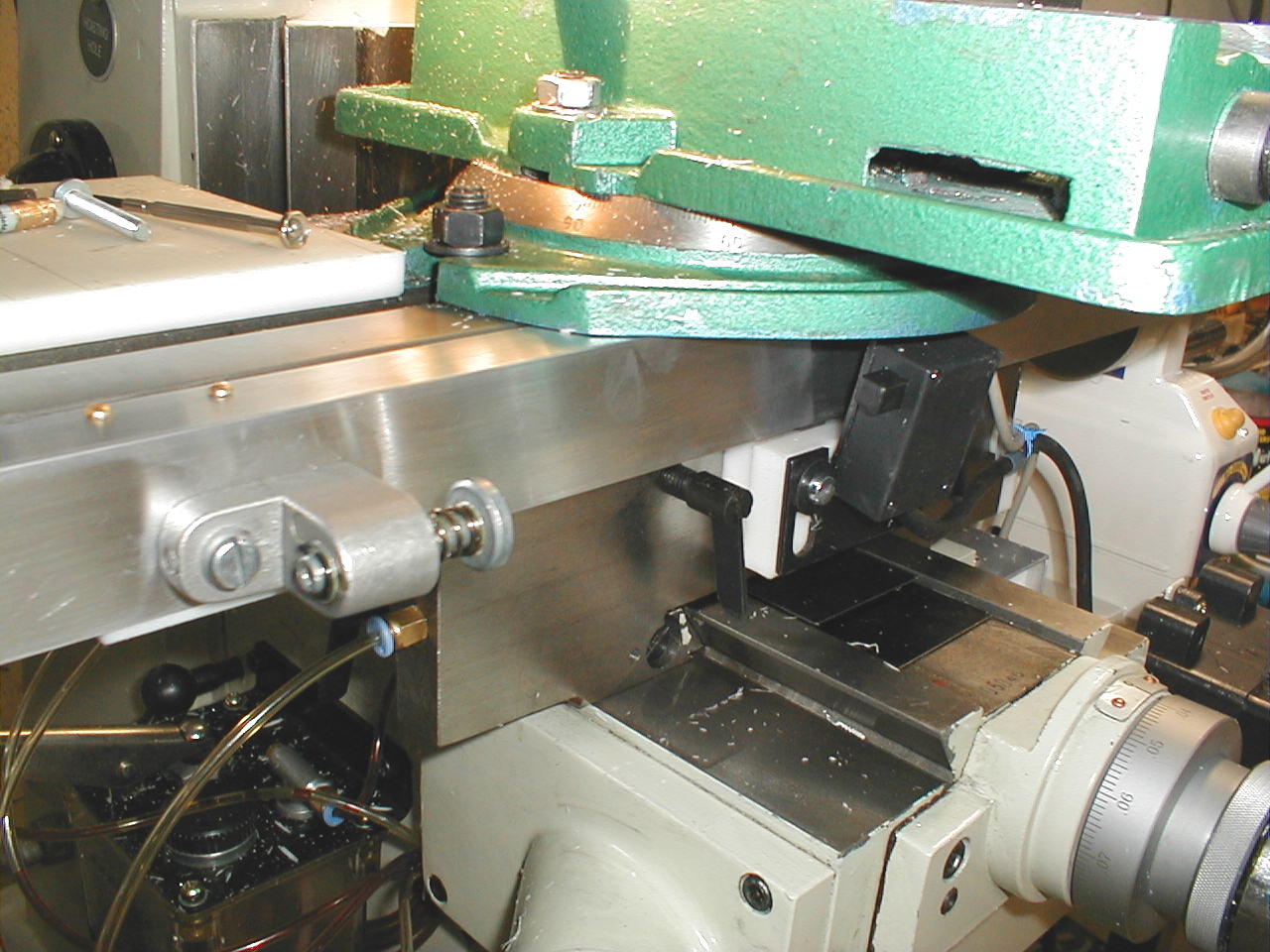 |
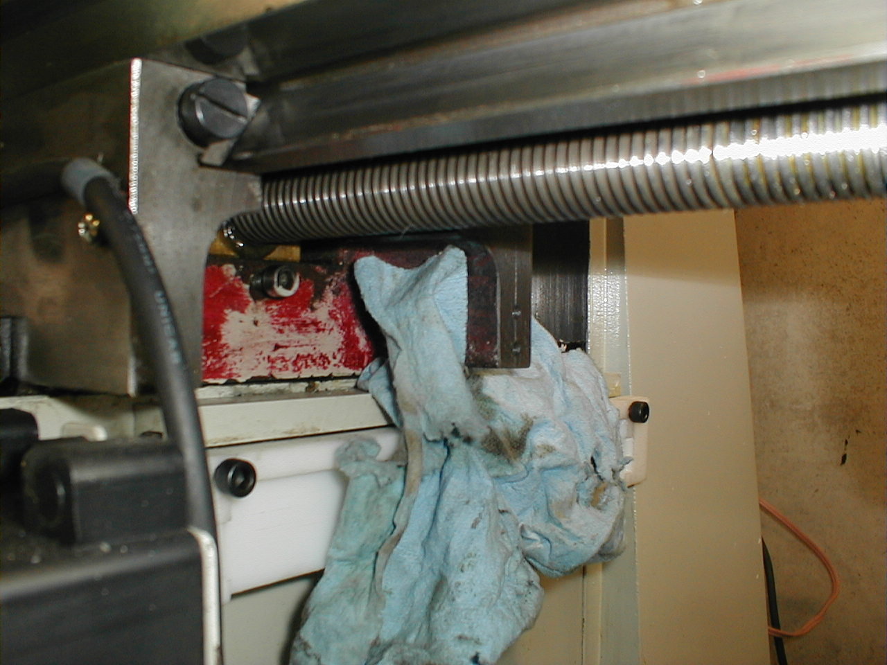
| The
limit switch is remounted and the bumper is put in place. With
the temporary scale, my X axis was limited to just under 13 inches
until the new scale arrives. |
 |
| Testing
the read-out while still working on the bumper for the right side of
the X axis. |
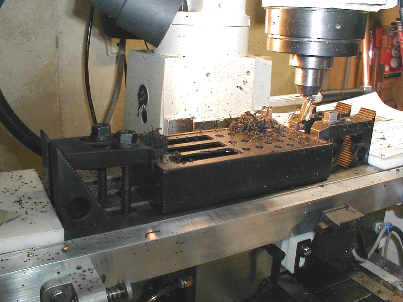 |
| Using
the DRO for its first task. Cutting its own housing! |
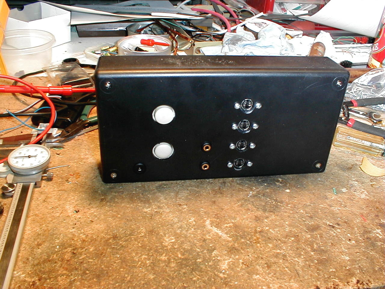 |
| Wiring
the housing. The white circles are switches to switch between two
scales on the Z axis and to choose either RPM or electronic edge finder. |
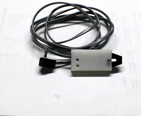 |
| This
is the Fairchild photo transistor for measuring spindle speed, housed
inside a liquid and swarf proof HDPE box. |
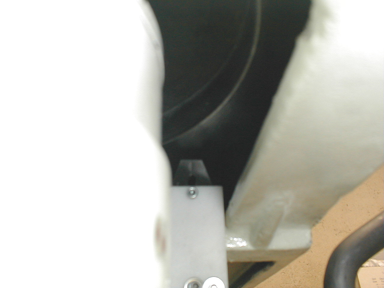 |
| And
mounted. Looking up at the under-side of the spindle pulley
(which is a lot more shiny than it looks here). |
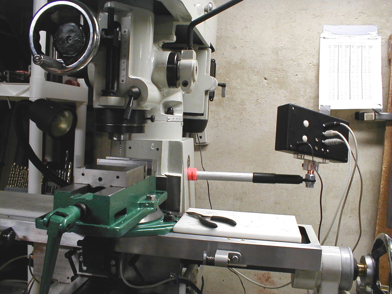 |
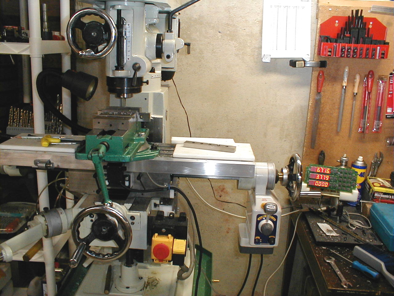
| An arm
holds the DRO in place and adjusts in length as well as allowing the
unit to swivel. |
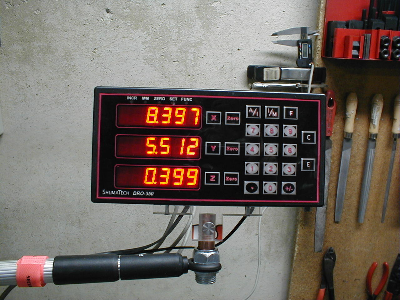 |
| Scott
was out of over-lays (and I wasn't crazy about the blue lettering
anyway), so I made my own. |
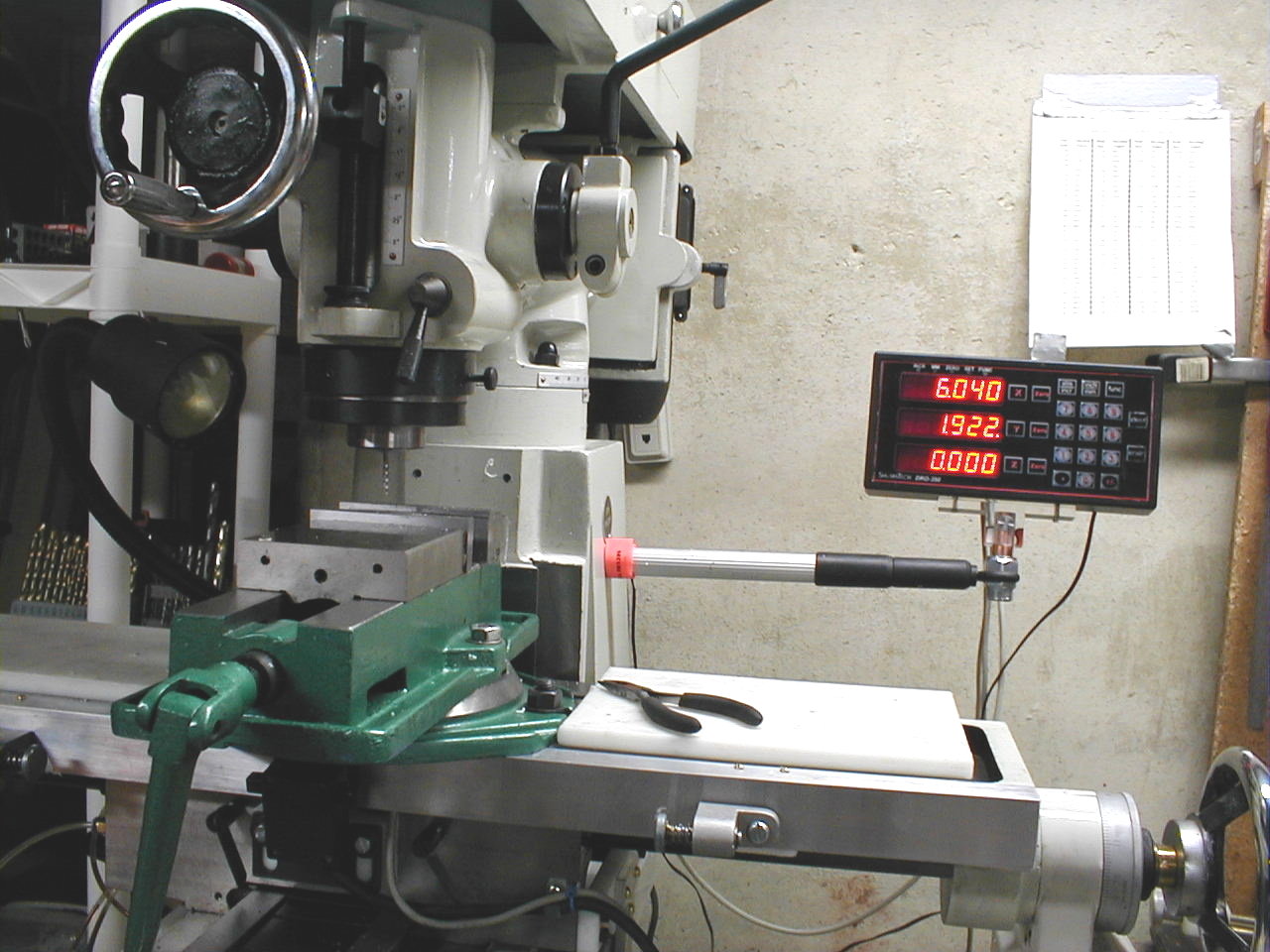 |
| Done
for now. Step back and admire one very cool DRO. My thanks to Scott for a useful and fun project! |