HOME
What's New


Workshop Stuff

Workshop

Moving the mill

Spindle Noises

ShumaTech Digital Readout

ShumaTech DRO Continued

ShumaTech
DRO-350 Repairs


South Bend 9" Lathe

South Bend 405 Lathe Bench

Grizzly Mill Revisited

Surface Grinder Rebuild

Surface Grinder Continued

Grinder April 6, 2008

Grinder April 20, 2008

Grinder August, 2008

Grinder September, 2008

Grinder November, 2008

Grizzly G3103 Mill
Rebuild

Grizzly G3103 Mill
Rebuild - Part 2

Moving the Shop

Moving the Shop 2

Bringing Home a Sheldon 12" Shaper

Sheldon 12" Shaper 2

Sheldon 12" Shaper 3

Sheldon 12" Shaper 4

Sheldon 12" Shaper 5

Sheldon 12" Shaper 6

Sheldon 12" Shaper 7

Sheldon 12" Shaper 8

Sheldon 12" Shaper 9

Way Alignment Tool


Email Jim


 workshop.gif
DoAll D624-8 Surface Grinder Continued
Weekly Updates

Week of April 20, 2008
I've finally received my SPI lap and another 50 carats of 3000 mesh diamond powder so I can finish up flattening the top of the granite straight edge.  However, before I can begin, I need to clean and check the lap to make sure it's flat and free from burrs.  I blued up the lap and set it on the surface plate.  It appears that this plate was ground pretty close to accurate, but it could still stand to be broken in a bit before I use it on the straight edge. 

Shipping issues?
Inside the wrapping
I usually don't ask a seller to do a extra nice job of packaging, but since this plate was 70 pounds, I did on this occasion.  This is what I got for my asking.  The cheap cardboard, coupled with the heavy handling that packages normally get, left this box a bit the worse for the wear.  Fortunately, the shipping gods were on my side (for a change) and the plate arrived without a scratch.  I still don't know how I got that lucky.

I got out my diamond powder roller, which is nothing more than a roller bearing that has been attached to an axle and bolted to an aluminum handle.  The procedure for charging then lap is to sprinkle some diamond powder on one area of the lap and use the roller to press it into the lap's surface.  I tend to think that I get better results if I use a lot of pressure on the roller, but with the hardness of the diamonds, they will embed even if moderate pressure is used.  Using a larger roller would speed up the process some, but my next step also helps embed more of the abrasives.

The next step was to empty the loose diamond powder from the lap on to the top of the surface plate I have been reconditioning.  Using a coarse camel-hair artist's paint brush, I spread the powder out to form a square the size of the lap.  The lap is then placed face-down on the surface plate and pushed and twisted into the powder.  At this point the lap is lifted off the plate and the roller is used again to press more diamond powder into the lap.  The process is repeated until the surface of the lap shows a uniform coat of the abrasive.  The diamond powder pressed into the lap shows as a dull finish in contrast to the new shiny lap.

I wanted to try a test run on the old surface plate before I started lapping the critical top surface of the straight edge.  This would give me an idea of how much granite will be removed in a few passes.  Generally one thinks of lapping metal as a surface finishing technique that removes very little material.  However when lapping granite, my experience tells me that even with a rather fine 3000 mesh powder, I can remove enough material to change the surface topology substantially.

I have mapped the surface of the surface plate I am reconditioning by drawing a grid of 2" squares that correspond to locations on the plate and using my shop made planekator copy I have record the relative height of each corner and center of each square.  After looking at my map and finding the high points I needed to lower, I tried out my new lap by rubbing it over the high spots and feathering them into the areas that I needed to take less material from.  After a few passes, I removed the lap, cleaned the plate and remeasured.  After noting all of the relative heights on the map, I found that I had been successful in lowering the highest spots by a couple ten-thousandths.  I had also achieved my other goal of breaking in the lap.  The lap's surface was now quite dull where it had been in contact with the surface plate and less dull in the lower areas of the lap.  The pattern on the lap of dull and less dull was pretty even and the area I had reworked on the surface plate was smooth and uniform.  I was ready to work on the granite straight edge.

Since I didn't have much of a height difference between the highest and lowest areas on the top of the straight edge, I chose to not recharge the lap.  I have read that by not having any loose diamond powder on the surface and only using the
diamonds embedded in the lap that one can achieve a smoother surface with less variations in surface elevation.  Since this was what I was trying for, I gave it a shot.

New Lap
Plate is level
End View Straight edge is level
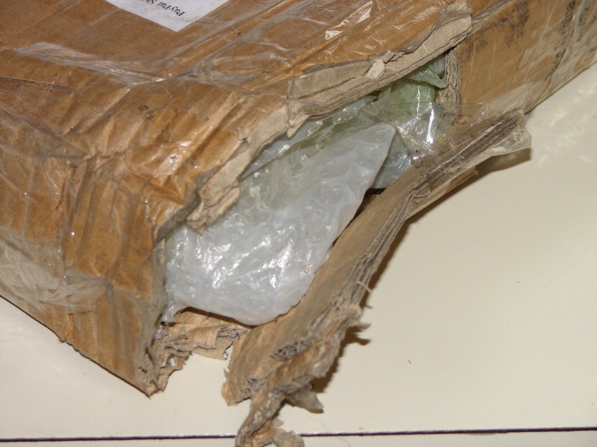
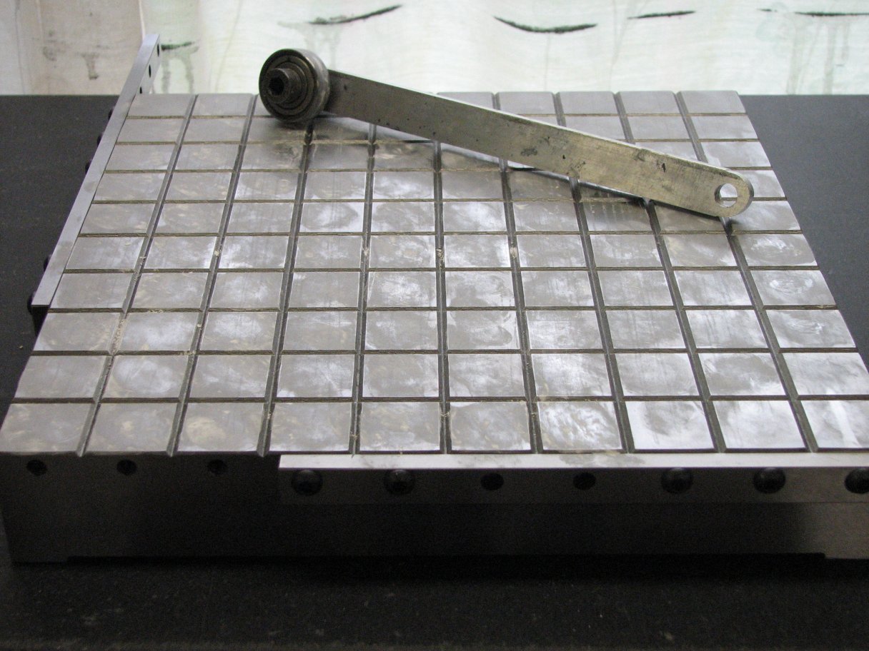
With a ball bearing roller to apply the 3000 mesh diamond powder, I rolled it in as evenly as I could.  I then did a practice run on my carefully mapped old surface plate.  I then reapplied more diamond powder and carefully lapped the top of the granite straight edge.  After checking level in front and behind the straight edge, I checked the top surface of the straight edge.  After a couple cycles, it was level and smooth.

After a few passes on the top surface of the straight edge, I set up my measuring gear so I could check the relative height of the top surface.  This turned out to be as close to zero difference in height as I can measure.  For the last check, I leveled my new 
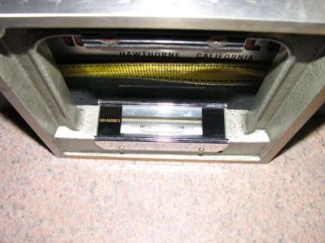
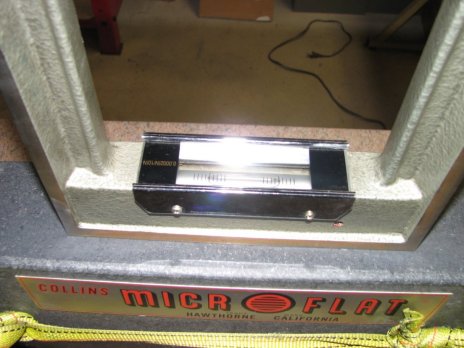
Starrett surface plate with the straight edge centered on it.  When I had the bubble centered on my 0.0002" per 10" box level while on both sides of the straight edge, I placed the level on the top surface of the straight edge.  In this position, the level also centered the bubble.  This was no surprise since the Supramess indicator that I used to measure the relative height of the top surface has much better resolution (20 millionths) than the level, but I was happy for the confirmation none-the-less.

So, one more mini-project is done and I now have a way to check level between the separated ways of the surface grinder.  This should help me to make sure that both the saddle and table on the surface grinder stay level and square with the vertical column.  As a part 
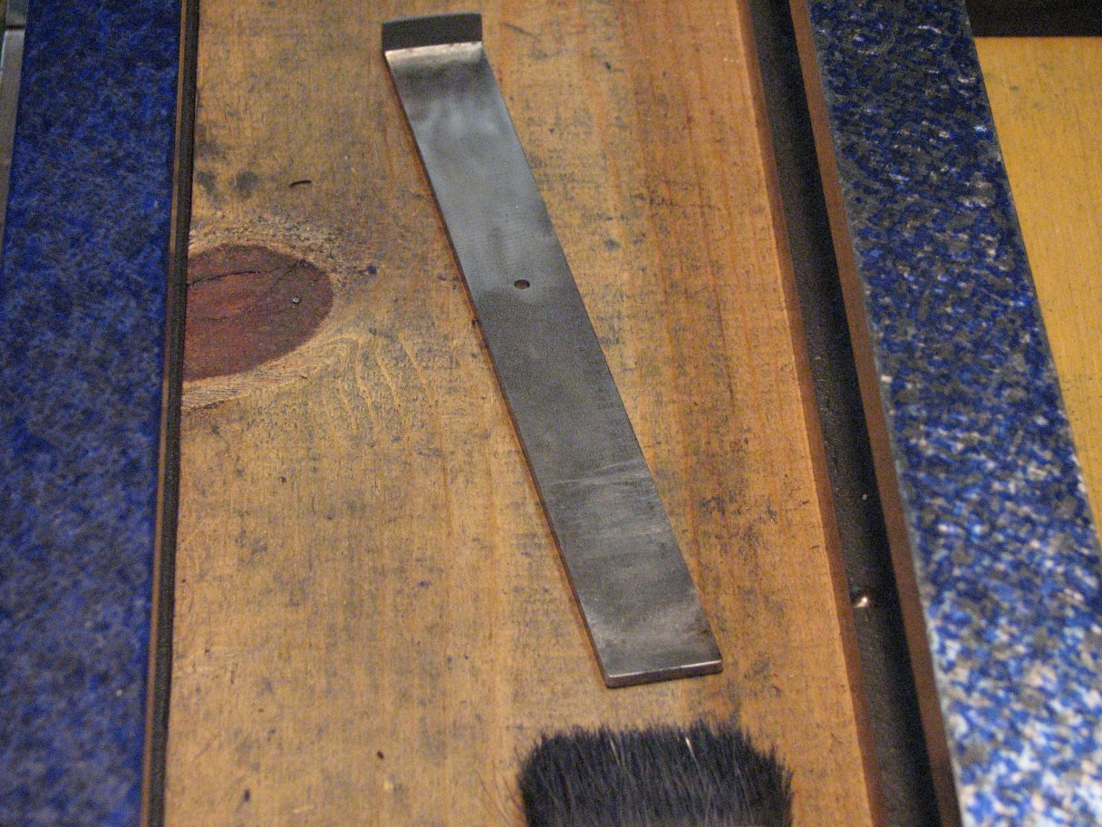
of the project, I have now acquired a lap that I will use only for 3000 mesh diamonds.  The 3000 mesh diamonds leave a pretty nice finish on granite, but it would be nice to have one more lap that I can devote to 5000 mesh only for situations where I would prefer an even finer finish.


Week of April 27, 2008
With the granite straight edge now finished, it was time to return to scraping the two cast iron straight edges that will be used to confirm that my granite straight edge's bottom surface is as flat as is needed for functioning as a scraping master. The first one I started on about 3 weeks ago and it has progressed to the point of being almost done with a pretty consistent 20 to 30+ bearing points per square inch when spotted on the granite master.  It is still not quite as smooth as I would prefer but it's getting there.

The second cast iron straight edge progressed much more quickly by using a pull-type scraper.  As I see it, there are a couple advantages and a couple disadvantages to using a pull scraper.  On the plus side, I have more control pulling than I do pushing.  For me, this means that it is easier to stop a pull stroke than a push stroke.  This results in each scrape being only as long as the high spot I am trying to remove rather than extending past the high spot into the surrounding area.  Another advantage is the depth of cut.  When using a pull stroke, it is easier for me to keep the depth of the cut constant than it is when pushing.  When I have progressed to taking shallow cuts, I am less likely to gouge the surface when pulling.  On the flip side, it is more difficult for me to work close to edges with a pull stroke.  Pushing the scraper off an edge at a 45° angle while holding the edge of the scraper parallel to the surface of the plane being scraped can be mastered fairly quickly.  Pulling the blade on to an edge at a 45° angle with only a small amount of the blade actually in contact with the surface being scraped and trying to keep the blade parallel to the scraped surface is much more difficult for me to master.  The tendency is to gouge the edge as the scraper is pulled on to the surface.  One answer is to only pull the blade off of the edge rather than on to the edge, but there are times when this isn't possible.  The other disadvantage of the pull scraper that comes to mind is trying to use it for scraping near the vertex of an inside dovetail.  A push scraper with its thin blade will fit much deeper than the thicker profile of a pull scraper.

Disadvantages aside, pull scraping the cast iron straight edge that I can move around to get the best angle of attack was the quickest that I have ever scraped from rough to almost surface plate quality finish.  It took only about 4 days at 3 hours work a day.  I was simply amazed at how quickly the surface improved.  Since my main reason for scraping the second c.i. straight edge was to test it against the other cast iron straight edge and prove the flatness of my granite master, I was checking it against the other straight edge as I scraped each cycle.  With the two c.i. straight edges spotting each other, it was looking very good.  The pattern of high spots I received while spotting against the almost finished cast iron  were very similar to the patterns I received when spotting against the granite master.. By the end of the forth day, the pictures below were taken.  If you click to enlarge them, you'll see how well the prints match.  The prints are a bit exaggerated by the use of more Prussian blue than necessary, but that is the only way the camera picks up the patterns.  When I spot with the bare minimum of blue, the color transferred to the clean straight edge is even and shows that the two cast iron straight edges fit together almost as well as each cast iron fits to the granite master.  Unfortunately, I am not able to produce a good picture of the very faint markings.

Cas Iron on Granite
Close up
More detail
Left: Cast iron straight edges spotted on each other.  Center: Closer view.  Right: A nice pattern showing that the two cast iron straight edges print as well on each other as they do on the granite master straight edge.  The one on the left (first pic), bottom (2nd), left (3rd) was pull-scraped and took about a third the time to do.

.
May 04, 2008
This past week and the next week are going to be pretty slow on progress in the shop. Our son graduates from the Army's Ranger school and we'll be in Georgia at Fort Benning for a couple days.  Congratulations Michael!  It's also time to do the spring maintenance on the vehicles, yard and whatever other around the house projects need to be done.  Hopefully these won't take too long as I would like to get beck to scraping the inverted V ways on the grinder's table.  It is also getting close to time to check my progress on the table against the grinder.  This will involve some leveling and a lot of measurements.  The timing for this project pretty good as I am just finishing up on reading
Fundamentals of Dimensional Metrology by Ted Busch and will be trying to keep a lot of what I've learned in mind.

May 11, 2008
Back to work on the surface grinder.  I'm about ready to start another mini-project to help me keep the table ways in alignment with each other.  I have been wanting to buy a King-Way alignment system for a while now.  Unfortunately they don't come up on Ebay very often and when they do, even the ratty ones with missing parts seem to sell in the $300.00+ range.  With the prospect of getting one at anywhere near a price I can afford is not too good, I have decided to build one.  There's a patent drawing of the tool here that will give you an idea of how it looks and works.  It is really a pretty simple concept.  There are two upright posts that attach to a cross-bar.  On the cross-bar there is a two axis spirit level.  On the bottom of one upright, there is a heavy walled tube with a slot cut lengthwise.  This slot will ride on an inverted V way or the sides of the tube would ride between the sides of a non-inverted V way.  On the bottom of the other upright, there is a steel ball that rides on a flat way.  A steel ring of a slightly smaller diameter can be placed under the ball if the flat ways are too dinged up to rely on the single contact point of the ball.  By leveling the tool, then sliding it along the ways, one can see if the ways remain parallel to each other by observing the level's bubble. Since my smallest precision level (6") has only one vial, I will only be able to measure one axis at a time, but this does not diminish the usefulness of the tool.  I will be on the lookout for a two axis, 0.0005" discrimination spirit level to take the place of my single axis one.

I have already made a mock-up of the tool using two dial indicator holders with magnetic bases, my 6" level, and some odds and ends and even this crude setup is a great help in keeping the inverted V ways of the surface grinder table parallel with the flat way that has already been scraped flat.  Building a copy of the King-Way will reduce the number of parts in comparison to my mock-up and less parts equals less chance of alignment errors.  Once I've gathered all of the pieces I'll need to build the tool, it should be a pretty quick project.  If you're interested in reading a bit more about the King-Way alignment tool and taking a look at the original instructions that came with the tool, there's a thread at Practical Machinist that's worth reading.

Grinder 1
Grinder 2 Grinder 3 Grinder 4 Grinder 5 Grinder 6 Grinder 7