
|

 |
Spindle Troubles December 12, 05 It's hard to believe it's been two plus months since I last updated, but then again, I do loose track of time when I get involved with a project and I have had quite a few projects going on. The topic for this time will be spindle noises. The cause of the spindle noise may be the biggest reason to be wary of the Chinese mills. As with any new possession, it takes awhile before you get to know it and are able to distinguish the individual noises that make up the machine's sound. From the first time I cranked up the mill, there was a clicking, or maybe better described as a clacking, if the change from the letter "i" to an "a" denotes a deepening in the pitch of the sound. The clacking was rhythmic -about once per revolution - and came from the area of the quill. The noise was more prevalent when there is no load or a light load on the spindle, but it returns on heavy loads with a different,deeper pitch. |
 |
My thoughts began to gel about the
noise when I noticed a poor finish on some aluminum stock while making
a relatively heavy cut. After stopping the machine, I grabbed the
end mill holder in one hand and the pulley in the other and twisted
them in opposite directions, then reversed the direction of my
twisting. There was play, just as I suspected. At this point
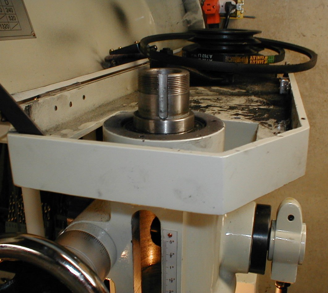
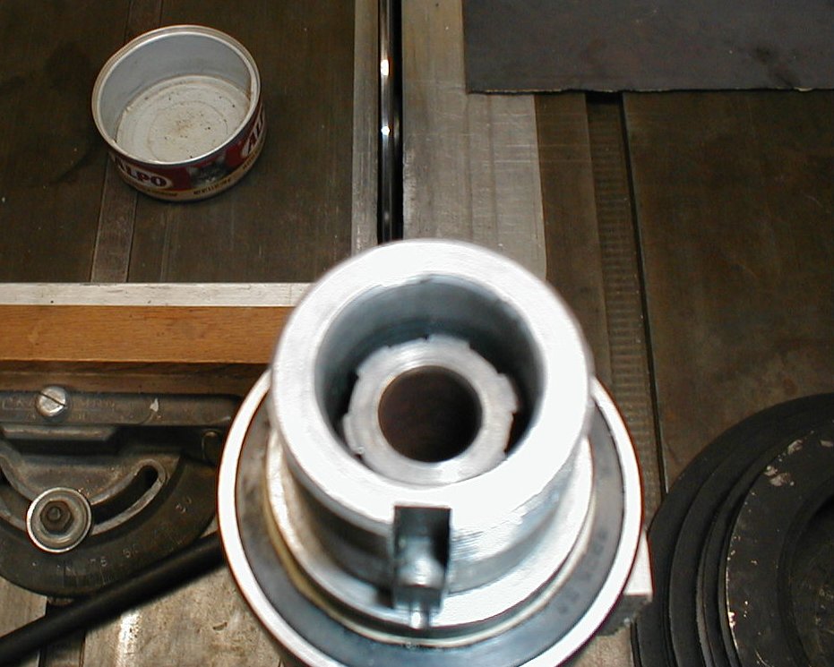
I probably had no more than about 20 hours total work time on the mill. Time to remove the spindle assembly and see what's up. To remove the spindle, the spindle pulley has to be removed. Remove the belts and the draw bar, then remove the large nut after bending the locking tab out of the way. A couple of screwdrivers or small pry bars can be placed on either side of the pulley and a sharp push or pull on both will break loose the pulley from the spindle sleeve (pic 1). Remove the bearing plate bolts and the bearing plate, then thread the nut back on a few turns down. Use a couple wood blocks on either side of the spindle sleeve as the fulcrum and pry out the sleeve. Mine came out without much drama. |
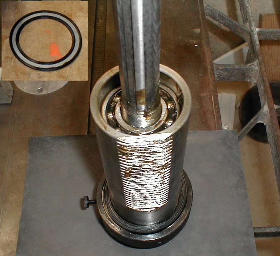 |
The sleeve has a pair of bearings
attached to it. These are a press fit, so unless you have an
arbor press, you don't want to try to remove them. You can remove
the plastic grease seal(insert
in pic 3) by inserting
a small flat bladed screw driver between the seal and the outer bearing
race and pop it out. Be careful not to bend it as it has a metal
backing and it's tough to flatten it back out if it gets kinked.
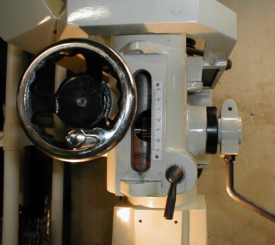
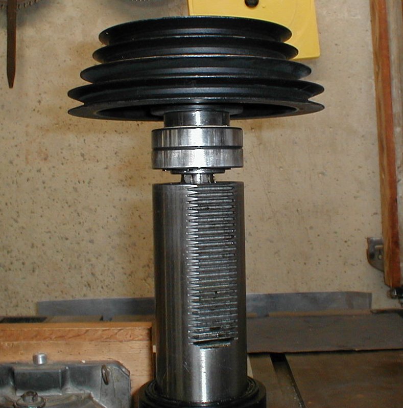
We'll get back to looking at this part in a bit. Next comes the spindle assembly. The easiest way to remove it is to remove the threaded quill stop assembly (missing in pic 2) and the block that attaches to the spindle, then loosen the quill lock. Place a board or something to protect the table under the spindle and start pulling down the lever that extends the quill. Once you reach about 6 o'clock, the spindle will fall out. The spindle is pretty heavy, so make sure that you catch it or stop its downward travel with a block. |
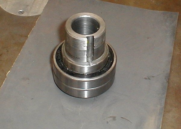 |
Once
the spindle is out, you can check the pre-load on the
bearings. Mine was a little on the loose side. With the
adjusting nut off,you can pop the seal on the bearing to check and see
what the lubrication looks like. Mine was very waxy looking, so I
cleaned and repacked the bearings with a high quality bearing grease
before I reassembled the spindle into the mill head. Unfortunately, I don't have a picture of the next step, so I will try to explain what I did to temporarily fix the noise. (The red in the drawing is a top view of the spindle shaft and the black is the spindle sleeve.) The spindle sleeve fits over the splined shaft on the spindle. There are 6 splines on the shaft that fit into a six-sided hole in the spindle sleeve. The noise comes from too much lateral play in the hole to spline fit. There has to be some play between the parts to allow the spindle shaft to move up and down when you raise and lower the quill, but too much will let the shaft "jump" in the direction of rotation on a heavy cut. |
 |
Too
much play between these parts is also a common problem in worn out or
poor quality drill presses. I have heard of, seen, and tried a
few ways to get rid of this play - or at least minimize it, but the
bottom line is that the shaft and sleeve need to be replaced. In
the case of my Grizzly, the amount of play could be changed by rotating
the shaft inside the sleeve. Rotating the shaft 180 degrees
almost completely removed the play. This doesn't say a lot for
the accuracy of the machining of these parts, as one would think
that the broaching of the slots in the spindle sleeve should be
equidistant from the center of the hole and the machining of the shaft
would also be at a constant depth. There is always the
possibility that I got a machine with a shaft at the thin end of the
specs and a spindle sleeve at the wide end, but it doesn't say a lot
for the selection process when the fitter matched up these two pieces. I needed to finish the part I was working on, so I needed to get rid of as much play as I could. As I said, rotating the shaft a half turn got rid of a lot of the play and I removed the remainder by center-punching a couple of points along the two thin splines. This is NOT a recommended repair, but it did expand the splines enough that eight weeks later, as I write this text, there is still no play in the spindle. |
 |
Grizzly
has been good about getting the rusty hand wheels replaced for me, so I
am fairly confident that they will get me a matched shaft and sleeve to
repair this problem when I get around to writing them about
it. This does not seem to be an uncommon problem with this style
of mill. A couple weeks back, there was a post in the 6X26
milling machines Yahoo group about a Warco mill with the same
problem. Warco sent the owner a new matched spindle, sleeve, and
shaft with all of the bearings installed to replace the out of spec
parts. If you found this page through a search engine and you have this problem with a drill press, I have seen instances where brass shim stock has been used on the trailing side of the splines to take up the play and still allow the shaft to move up and down in the sleeve. For my Craftsman drill press, I had a new sleeve broached and the shaft machined to remove the wear. |
 |
before
i started reassembling the mill, I took care of one other design issue
I had found to be lacking. The wedge that locks the quill didn't
seem to lock as positively as it could, so I removed it and filed and
sanded it to fit the profile of the quill. There is no quick way
of doing this, but having a drum sander that is about the same diameter
as the quill will speed up the process of reshaping it. You are
looking to get as much surface contact between the locking wedge and
the quill as possible. Being able to lock the quill tightly will
help the mill's accuracy a bit more. The last item I looked at is more a wish than something I can fix, but it would have been nice if the mill had some type of adjustment for changing the clearance between the gear and the rack on the quill. As it is, there is no way to adjust the backlash on the quill feed. It may be possible to machine a couple of eccentric bushings so that the gear shaft could be adjusted, but there is not a lot of room to work and locking the bushings would be a challenge. I cleaned off all of the old grease and repacked all of the bearings I could get to. |
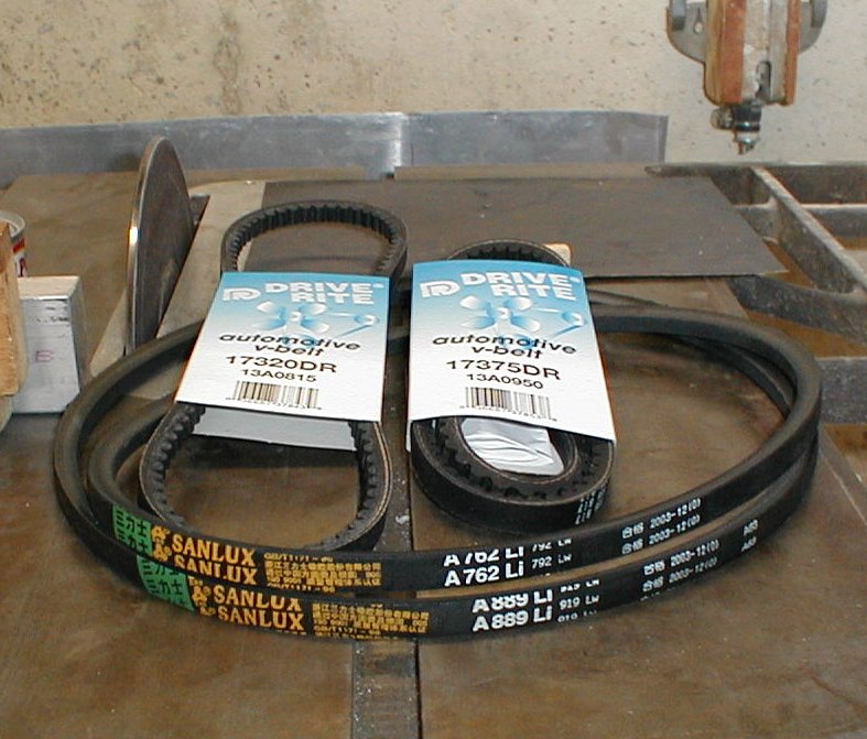 |
I had
also purchased some new automotive style v-belts so I could get rid of
the shedding belts(see
top image) that the
mill came with. I used a number 17320DR and a 17375DR. These
fit perfectly and don't shed so much rubber. After a couple hours work, the mill was back together and the difference was quite noticeable. First, the mill was quieter. No more click or clack. Second, the finish of the cuts was noticeably smoother. Not too bad for a few hour's work. Table Covers Having an end mill drop out of a collet on to the table happens. Dropping bigger things happens too. What can I do to stop dinging up the table besides being less fumble-fingered? Table covers, of course. I can't remember who to attribute this to but I saw it somewhere online and thought that this was a great idea, but it wasn't until I was given a couple white plastic cutting boards, that I had the material to make them. The cutting boards are the same to the ones shown here: http://www.chefdepot.net/cutbrd.htmexcept that the thickness of the ones I was given |
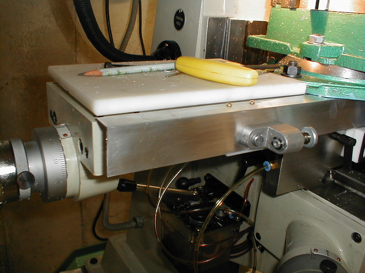 |
are
about 5/8". (You can find these at reasonable prices one
bay.) I made a slot on the under-side that is the same width as the slots on the table and inserted a 3/4" stringer. This holds the cover firmly and still allows it to be removed easily. The polyethylene is a strange material to cut. It leaves strings of plastic along all of the milled edges, but these can be knocked off with a file or an exacto knife. I decided I liked working with this stuff and since I had a couple 24" by 18" sheets, I used it for mounting the scales for my DRO project. The poly was great for the scales as the scales are positive ground and other folks have found that you get less "jitter" from the scales of you isolate them from the mill or lathe. All in all, a quick project that is already saving my table from harm. If you take a look at the front of the table in the last image, you'll see some angle aluminum. This is the "protection" for my most recent project. A ShumaTech DRO-350 digital read-out for the mill. I am to the point of machining the case and making up a face plate. It's been a great project. I should have the write-up done in a week or so. ~ Jim |