
|
| HOME What's New
Camera Stuff
|
|
The Sound Story
The program Motion
does not include the ability to use sound, though it is something that
some of the members of the mailing list have talked about. I had
been
thinking about this for a while and started researching the
possibilities. I would have to attack this problem on two
fronts. One, build a stereo preamplifier to allow dual
microphones to feed the sound card and two, find a way to make
Motion capture sound.
Little did I know that finding a preamp
circuit would take months of testing circuits on a
breadboard before I found a circuit that would work well with my Aureal
8820 sound card on my aging Linux box. I built prototype
preamps with single
transistors. I
built preamps with a couple ICs and a few transistors. I think I have
looked at almost every microphone preamp on the web and I have built
many of them on a protoboard. With all of the preamps I
built, I found
myself going back to a simple circuit that was adapted from the data
sheet for the LM386N audio amplifier integrated circuit. This circuit
stayed built on a protoboard as a mono preamp so that I would have
sound on the mpegs I collected each day. In between
builds of other preamps I messed around with this one trying to get rid
of the noise in the circuit. In the end, I got rid of most of the
offending noise and even though it was by no means the most powerful of
the preamps I built, it was enough to get the job done. I also
came up with a simple way to
get rid of the nine volt battery that was used in these circuits.
I came up with the power circuit idea
after being frustrated by the fact that a 9 volt battery would only
last a couple of days running 24/7 and running an auxiliary power
supply introduced a lot of hum into the sound card. I was
thinking
about the problem one evening and thought that using the power supply
for the computer that the sound card was in would mean that the ground
circuit was common to both the amp and the sound card. Since
grounding issues are what usually introduce hum into an audio circuit,
this just might do the trick. I didn't have a 9 volt voltage
regulator on hand, but did have a LM317 adjustable voltage
regulator. I built a circuit using the schematic on the data
sheet and was pleasantly surprised when it turned out to be as quiet as
using a 9 volt battery. Pretty cool! One major problem
solved.
I went through a couple different ideas
on microphones. I started with a couple condenser mics from Radio
Shack. I mounted the mic capsule inside a metal tube for the
first try.
 |
 |
 |
This ended up sounding -
well, like a microphone in a tube! Who would have thought?
I then tried a different approach. I used the reflectors from a
couple cheap flashlights and put the microphone button in the area that
would have housed the light bulb. I cut out a mounting plate from
some scrap fiberglass and using an old radio controlled car builder's
trick, I dyed the fiberglass with clothing dye. Not only does it
look better, it works better as well.
 |
 |
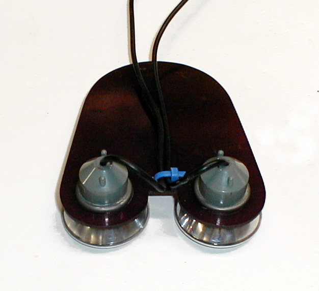 |
This mount will attach
behind the camera with the microphones below the camera housing.
The mics are angled so that they face out from center. This helps
a bit in being able to separate the left channel from the right.
My friend John tells me that the setup looks a bit lake a brassiere,
but I figure that's just wishful thinking on his part! The mics
are rubber mounted in the fiberglass and this does a bit to isolate the
mics from the rumble of the stepper motors. It also makes it
possible to angle the mics about 15° from perpendicular to
the mounting plate.
With the mics in a better
state, it was back to the preamp circuits. I came across a kit at
Jameco called the Super
Snooper and had high hopes for it, as it was designed to listen to
voices at a distance. Since my goal is to be able to incorporate
the ability to point the camera in the direction of sounds coming from
my property, I was hoping that this circuitry would be sensitive enough
to serve my purpose. The PDF file has a decent shot of the
circuit board, so it was pretty easy to duplicate the
circuit. This circuit uses a LM386 audio amp and a LM1458 OP-Amp
along with a condenser mic. Unfortunately, it didn't produce a
whole lot more sensitivity than using the LM386 alone. I was a
bit surprised that the Jameco kit did not make use of jumping pin 1 and
8 of the audio amp to increase its output - though the circuit board
does have traces provided to add a 10µF cap to increase the
voltage gain to 200.
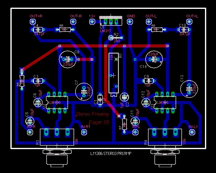
So it was back to the
drawing board, or in this case Eagle software's Eagle 4.14 light
to draw up another circuit. At the same time, I started doing
some reading on how to etch circuit boards. There are a couple
types of kits available for etching circuits on copper clad circuit
boards. Radio Shack sells one with a Sharpie permanent marker so
you can draw your layout, then etch away the un-needed copper with the
supplied Ferric Chloride solution. This may work well for very
simple circuits, but the pen doesn't draw a sharp enough line for
circuits where the traces will be very close together.
Another choice is to use
one of the kits from Jameco or Allied Electronics that use a
photo-sensitive coating on their copper clad blank boards. For
this type, you design your circuit using a tool such as Eagle 4.14
lite, then print it to a transparency, then place the transparency over
the board and expose it with either sunlight or a UV lamp, then
develop the board and finally etch it with either Ferric Chloride or
Ammonium Persulfate. This supposedly gives much better results,
but I had read about using circuits printed on special paper with a
laser printer, then ironed on to the circuit board blank. This
works because the toner used by the laser printers is a powered
plastic. When heated, the powder melts and forms a thin plastic
film over the paper in the shape of each character. As long as
you use a paper with a slippery finish, such as photo paper, applying
an
iron to the back side of the paper will transfer the plastic image to
the circuit board blank. This sounded like it would be the easiest way
to go.
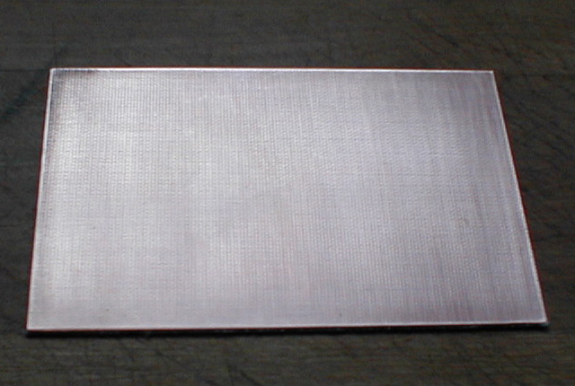
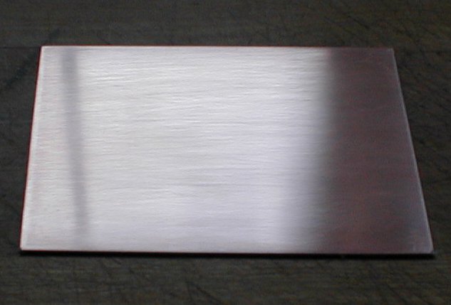
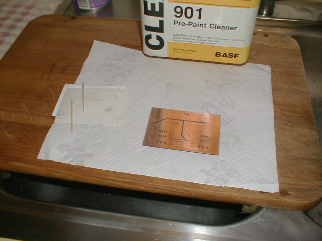
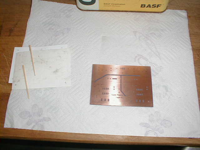
I purchased the Radio
Shack etching kit. Once I opened the package and looked at the
board blanks, I noticed that instead of being totally smooth, they had
a texture to them. I though that this might prevent the process
of ironing the printed circuit to the board from working
properly. The "fix" was to use some 400 grit wet and dry
sandpaper, then some 800 grit, to sand the board as flat as I could get
it. This took about 15 minutes of sanding with water to wash away
the copper particles to get the 3.5 X 5" board nice and flat. The
sanding is also a good idea to clean the oxidation from the board
before trying to etch it. Below are the before sanding and after
sanding shots. It was tough getting the bumpy surface to reflect
with a flash, so I tried without one. If you enlarge the
pictures, you will get some idea of the difference.
 |
 |
I am no electronic
designer, but through all of the reading about audio circuits I have
been doing for the last couple of months, I am beginning to come up
with some designs that do what I need. The design I just
finished drawing up puts the capacitors and the volume control pots
very close to the IC chip to keep down the noise a bit. I am
getting a little better with positioning components on the board to
keep the layout compact, but I still have a way to go in that
regard. I enjoy working with circuits and think that I will spend
some more time learning when I finish up with this project. I
have read a bit about PIC microprocessors and think I would like to
spend some time getting familiar with them. Ah, so many interests
and so little time!
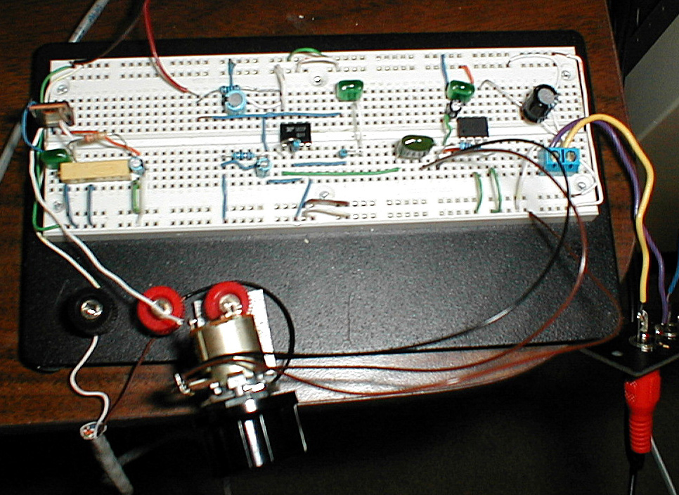
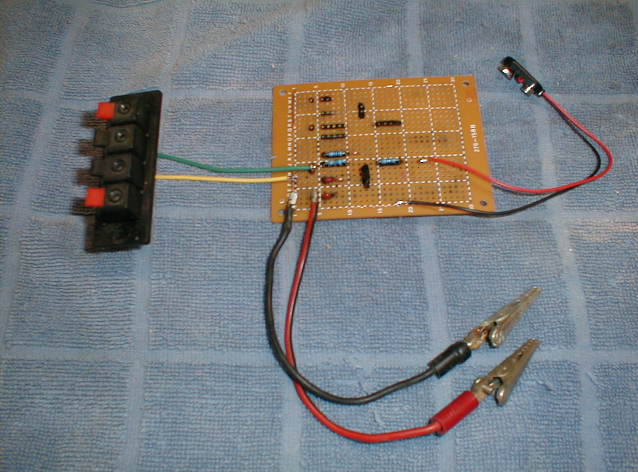
The next circuit I decided
to build was fairly simple compared to some of the earlier attempts,
but it was a design that had worked well at the breadboard stage,
unlike the "Super Snooper circuit that I borrowed from Jameco and the
two transistor amp circuit I found on an audio site. Below is the
Super Snooper circuit on a breadboard on the left, a quick and dirty
perf board two
transistor circuit and the final board design for the stereo LM386
board on the right.
 |
 |
 |
Back to the etching of the
circuit board. After getting the board flat, I cleaned it with
steel wool and an automotive prep solvent which is used to prepare body
work for paint. It strips off waxes and whatever else without
being too harsh. I had placed some drilling guides on the board
and drilled four holes to allow me to line up the top and bottom
circuit templates. This is a good idea if you want the top and
bottom circuits to line up with each other. I used a size #62
drill bit which is .038" (.9652 mm). Be forewarned, they are
quite easy to break.
My wife took the artwork
to work along with a couple of sheets of Epson All-Purpose Glossy
Paper, # S041654, and used their laser printer to print my circuits to
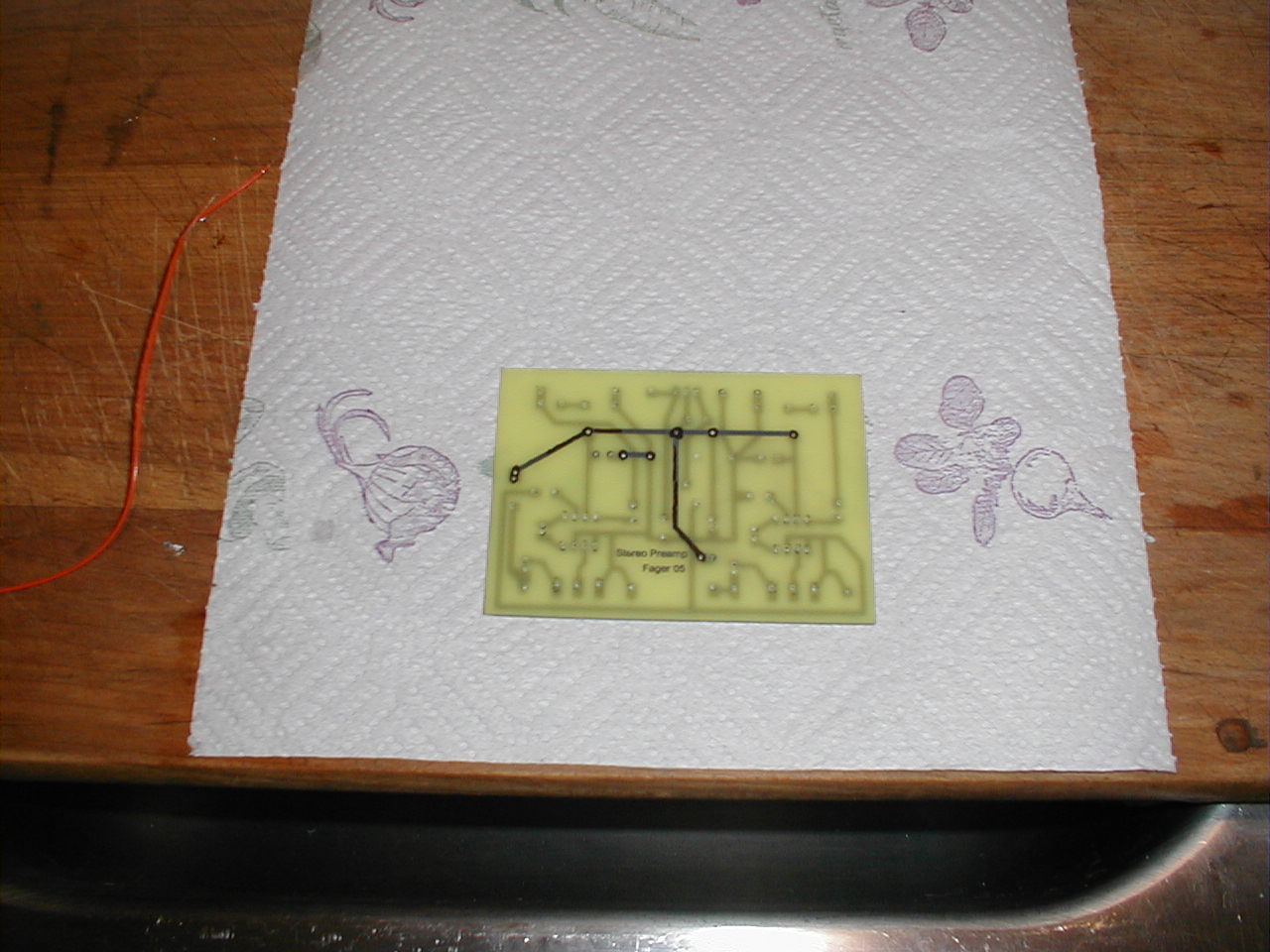
the shiny side. I then punched 4 holes in the bottom template,
which didn't need to be reversed for the printing, and in the top
template, which did need to be flipped over by Eagle 4.14 to print
properly. Starting with the bottom, I lined it up using
toothpicks and pressed the iron in the center of the paper to get the
toner to stick to the copper. Once the center is stuck down,
removal of the toothpicks allowed me to finish ironing the circuit
pattern to
the copper. I used just below linen on the iron's heat scale and
pressed down hard with the tip of the iron. It is possible to
gently pull back the paper to see if the toner is going on completely
or whether there are still bits attached to the paper and then return
it to its aligned place, but it is very hot. Once the transfer
has been achieved, you can move to the top circuit. Do NOT remove the
paper from the bottom while ironing the top or the toner will attach
itself to whatever is under the board. The paper has a wax-like
coating on it, so the paper doesn't stick to the board. Unlike
some of the instructions I read on the web, I didn't need to soak the
paper in water to get it off of the copper.
 |
 |
 |
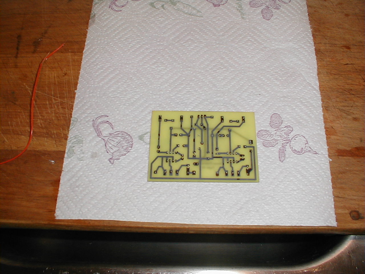
Once the ironing is
complete, let the board cool and remove the paper. Clean up your
mess (It's probably not YOUR iron, right?) and then touch up any areas
where the toner did not adhere with a Sharpie or other permanent marker
with a fine tip.
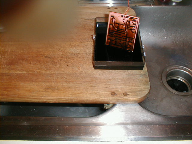
I then tied some string
through one of the holes I had drilled and stuck the board into the ferric chloride that had been
warmed up to about 100°F by sticking the bottle under some hot tap
water. I continuously agitated the solution and checked the
progress every few minutes. Even though this was the second time
I had used the solution, the etching went pretty quickly. I would
guess that it took about 10 to 12 minutes for the copper to be totally
dissolved.
 |
 |
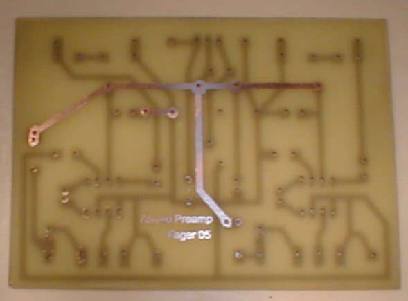 |
After cleaning the board
under running water and some dish soap, I cleaned the toner and Sharpie
ink from the traces with some lacquer thinner. The Radio Shack
kit
comes with some solvent to clean off the ink, but I already had the
lacquer thinner out and it worked so well, I didn't bother trying their
solvent. I'm pretty impressed with using photo paper and an iron
to transfer the toner to the blank circuit board. It did such a
good job that the printing that I placed on the front of the board was
sharp and clear. That's pretty neat considering that the letters
were only 1/10th of an inch tall. For my first attempt at using
this method, I consider it a complete success and can't even think of
anything I could try the next time to make it better - except for
planning better circuits. It turned out that my plan to solder
both volume control pots directly to the board wouldn't work. I
had miss measured the depth of the case by an inch. I have no
idea how I did that, but the board would not fit if I soldered the pots
to the bottom of the board as planned. I ended up having to mount
the board to the bottom of the case and attach the pots to the face of
the case and run short lengths of shielded wire between them.
It's not quite as clean looking as I had hoped - even though no one but
me will ever look inside the case.
Stuffing the board with
parts went quickly and the soldering was easy, thanks to finally
replacing the worn out tip of my soldering station. My concerns
that having to move the two pots from being soldered directly to the
board to being attached by a couple inches of shielded cable would
introduce some noise into the circuit were
unfounded. The circuit is remarkably quiet. The sensitivity
and clarity of the sounds it picks up are pretty good. With the
pair of mics mounted on the camera outside the computer room window and
that window shut, I can hear the radio being played at moderate volume
inside the room. I asked my wife and son to have a conversation
on the driveway and had no problem listening in, though that's only
about 40 feet away from the microphones. The separation between
the channels is good. It is easy to tell what direction cars
are moving when they pass the house.
Even though this phase of
the project, or should I say the project within a project, has taken a
lot longer than I had originally envisioned it would, I'm quite pleased
with the outcome. Besides accomplishing the task of building a
microphone preamplifier, I've learned quite a bit about amplifier
circuits, become pretty proficient working in Eagle 4.14 lite, and
learned a new (for me) method for producing a pretty good looking
circuit board.
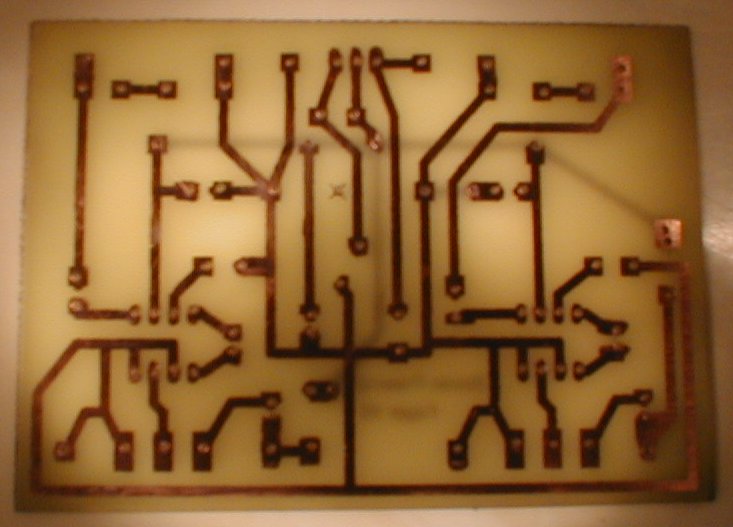
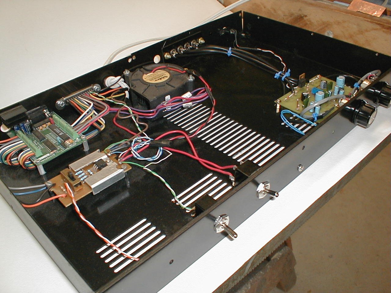
Below, left to right: 1)
You can see how well the top and bottom layers of the circuit board
line up. 2 & 3) The preamp takes its place in the little 1U rack
case, along with the BiStep A06 stepper motor controller and a multiple
output voltage regulator. There's still a lot of room in this
case. I just have to figure out what else needs to go in there.
 |
 |
 |
|
|
|
|
|
|
|
|
© Fager 7-31-05